Methods and apparatus for atrioventricular valve repair

a technology for atrioventricular valves and methods, applied in the field of heart valve repair, can solve the problems of valve insufficiency, serious complications, and possible death, and achieve the effects of preventing the degeneration of leaflets, reducing the number of patients, and improving the quality of li

Active Publication Date: 2012-05-08
CEDARS SINAI MEDICAL CENT
View PDF24 Cites 93 Cited by
  • Summary
  • Abstract
  • Description
  • Claims
  • Application Information

AI Technical Summary

Benefits of technology

[0016]The catheters each have a proximal end and a distal end. They may contain a central lumen that is designed for placement over a guide wire and they may be torqueable and flexible as required for their advancement via the left atrium across the mitral valve, through the left ventricular outflow tract, and across the aortic valve, where the proximal end may then sit in the ascending aorta. The route of the catheter thereby provides a means of predictable orientation of the catheter with respect to the papillary muscles, the anterior leaflet, and the posterior leaflet of the mitral valve. The shape of the catheter thus formed acts as a fulcrum about which the catheter can be easily manipulated with respect to the individual valve leaflets.
[0017]The orientation catheter has an inflatable balloon at its distal end and a central lumen for a guide wire, and is advanced into the ascending aorta from the left atrium. The placement of the catheter allows for the easy advancement of the other elements of the device through the mitral valve orifice, its chordal attachments, and the papillary muscles without getting entangled in these structures. A guide wire may be advanced through the orientation catheter, allowing other catheters of the system (such as the Housing Catheter) to be exchanged over this wire so that the position of the distal aspect of the device in the ascending aorta is maintained.
[0019]The Valve Immobilization Catheter has a semi-rigid portion that contains the leaflet immobilization apparatus. The leaflet immobilization apparatus contains two asymmetric leaflet immobilization supports, one optimized for the anterior leaflet and one optimized for the posterior leaflet with respect to size, angulation, and positioning along the length of the catheter system. The leaflet immobilization apparatus also contains two fixating members that allow for the independent securing of the individual leaflets.
[0022]In alternative embodiments, the catheters of the system may contain a pre-shaped curve to assist in advancing them through the left ventricle into the aorta.
[0026]In another method aspect, magnetic resonance imaging, fluoroscopy, and different forms of echocardiography, including transesophageal echocardiography including transesophageal echocardiography, transthoracic echocardiography, intracardiac echocardiography, and three-dimensional cardiography may assist with device position and advancement within the heart and body, leaflet immobilization, and the determination if the leaflet apposition achieved by the device is adequate.

Problems solved by technology

Valvular insufficiency may result from a variety of problems with the components which make up the valve—for example, the leaflets themselves may degenerate, the tissue cords which tether the leaflets to muscles within the heart may break, or the ring of tissue within which the valve is seated (called the “annulus”) may expand after heart attacks or from congestive heart failure.
Each of these problems leads to a common element in valvular regurgitation: when closed, the edges of the valve leaflets no longer fit snuggly next to each other and allow retrograde flow.
MR is a debilitating disease that can lead to serious complications and possible death.
Although open-heart surgery is a successful method of repairing or replacing faulty heart valves, it poses a significant risk to the well being of the patient, including death, severe injury, and disability.
There is a risk of ischemic or other damage to the heart and other vital organs resulting from the discontinuance of the heart's normal function.
The heart-lung machine may also cause abnormalities of the patient's circulatory, respiratory, hematologic and neurologic systems.
There is a risk of stroke and other consequences from emboli released into the blood during the surgery and during initiation of cardiopulmonary bypass.
There is a risk of heart attack.
Significant damage occurs to the tissues and bone retracted from the patient's chest while gaining access to the heart.
Consequently, a patient's recovery can be painful, discomforting, long in duration, and costly.
Moreover, a limited surgical approach or percutaneous approach would decrease or eliminate the tissue trauma that occurs from the extensive incisions of open-heart surgery, sparing patients pain, improving recovery time, and decreasing post-operative complications.
In addition, significant MR and / or TR complicate 30-60% of patients with congestive heart failure, contributing to their impaired cardiac function and causing significant morbidity.
However, because of the significant risks involved in open-heart surgery, many of the patients are unable to undergo valve repair.
No one, however, has successfully repaired the mitral valve of the human heart with a minimally invasive, beating-heart procedure.
First, the heart and its associated valves are not directly visualized or accessible.
One can use imaging techniques such as fluoroscopy or echocardiography, but these provide a two-dimensional image and a limited field of view.
Second, it is extremely difficult to immobilize the rapidly moving heart valve leaflets for repair purposes while the heart is beating.
Thus, no single device or methodology has successfully been used to repair heart valves in a minimally invasive manner on a beating heart.
The valve apparatus on the ventricular side of the valve—consisting of primary, secondary, and tertiary chordae tendinae and the papillary muscles—makes the manipulation of devices in this area difficult, and consequently the successful deployment of the device requires correctly negotiating the pathway through the valve without becoming entrapped within the cardiac structures and / or damaging them.
These described methods and devices are insufficient for properly and optimally capturing and fastening cardiac valve leaflets, because they do not describe methods or apparatuses that are sufficient to ensure the proper alignment with intracardiac structures, the independent immobilization of the mobile valve leaflets, and the fastening of tissues with specific leaflet geometry.
Thus, U.S. Pat. No. 6,165,183 does not describe a clinically feasible device or method for cardiac valve repair.
As such, U.S. Pat. No. 6,269,819 does not provide a clinically feasible or optimal approach to minimally invasive valve repair.

Method used


Image

  • Methods and apparatus for atrioventricular valve repair
  • Methods and apparatus for atrioventricular valve repair
  • Methods and apparatus for atrioventricular valve repair

Examples


Embodiment Construction

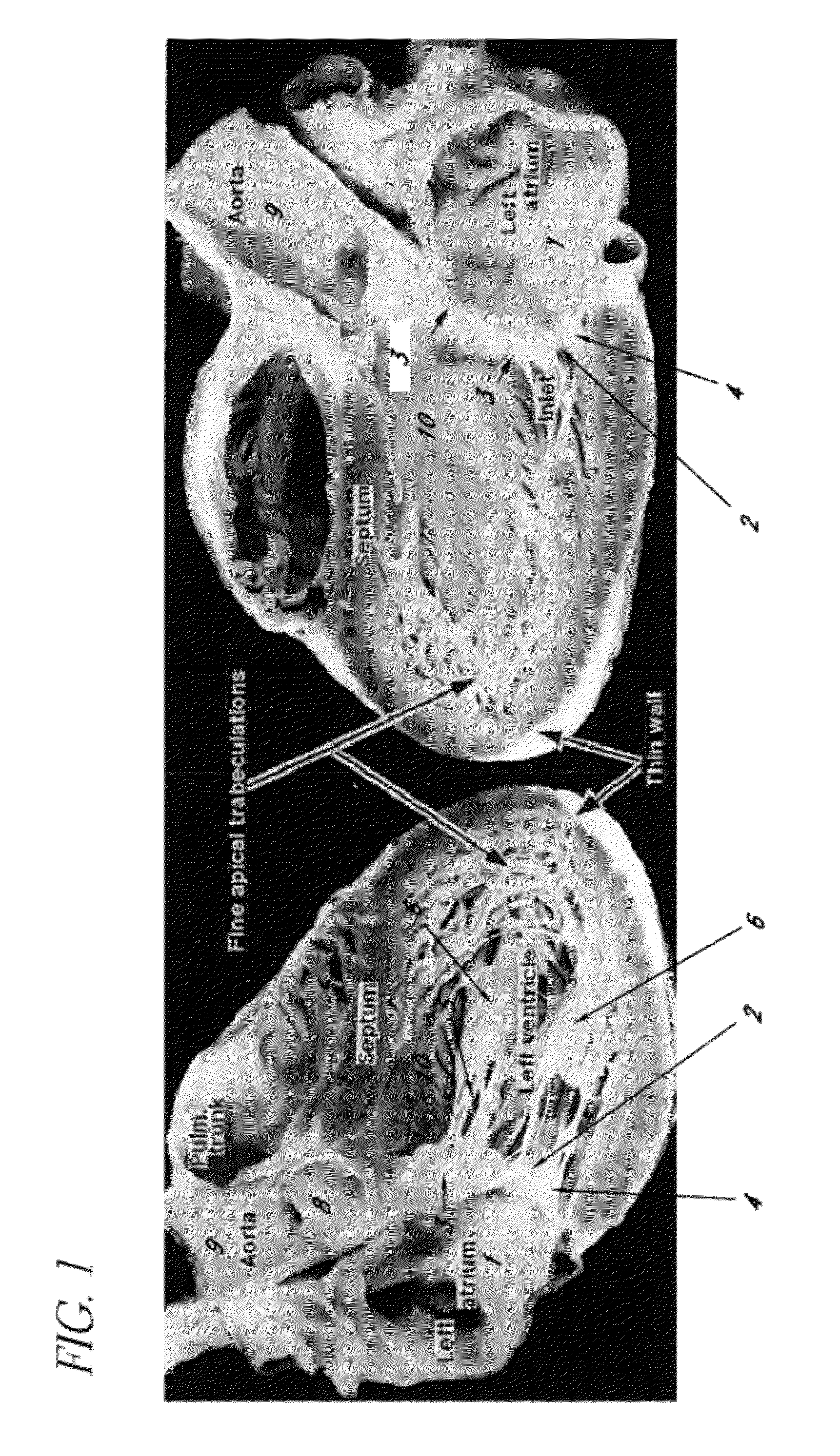
[0044]In FIG. 1, a longitudinal section of the human heart is shown demonstrating the left atrium 1, the mitral valve orifice 2, the anterior leaflet of the mitral valve 3, and the posterior leaflet of the mitral valve 4. The subvalvular apparatus consists of the numerous chordae tendinae 5 and the papillary muscles 6. The left ventricular outflow tract (LVOT) 10 is a channel formed by the anterior leaflet of the mitral valve 3 and the interventricular septum. This Figure demonstrates the pathway the distal end of the device must take from the left atrium 1, through the mitral valve orifice 2, between the papillary muscles 6, through the LVOT 10, across the aortic valve 8 and into the ascending aorta 9.

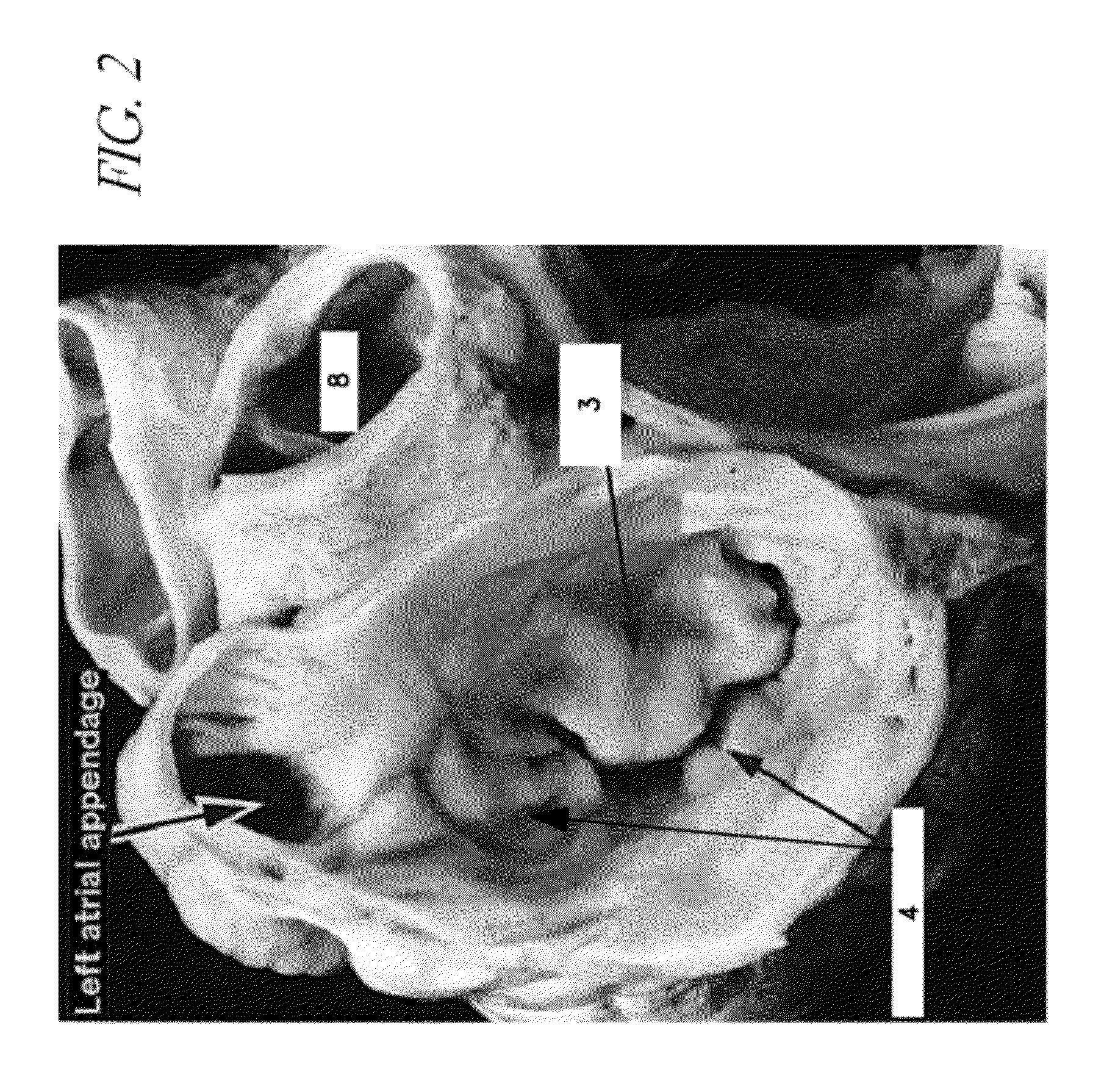
[0045]In FIG. 2, a short axis view of the mitral valve is seen at the level of the left atrium. This demonstrates the asymmetric nature of the mitral valve leaflets. The posterior leaflet 4 has a broad base and of narrow width, while the anterior leaflet 3 has a relatively narrow base...


PUM


Abstract

Methods and devices are disclosed for minimally invasive procedures in the heart. In one application, a catheter is advanced from the left atrium through the mitral valve and along the left ventricular outflow tract to orient and stabilize the catheter and enable a procedure such as a “bow tie” repair of the mitral valve. Right heart procedures are also disclosed.

Description

[0001]This application claims priority under 35 U.S.C. §119 to U.S. Provisional patent application serial No. 60 / 400,840, filed Aug. 2, 2002, the disclosure of which is incorporated in its entirety herein by reference.FIELD OF THE INVENTION[0002]The present invention relates generally to the field of heart valve repair. In a preferred embodiment, the invention relates to heart valve repair for patients suffering from mitral and / or triscupid valve regurgitation. It is a method and apparatus for repairing a cardiac atrioventricular valve consisting of a catheter(s) / guidance system that uses the position of a leaflet immobilization device in the ventricular outflow tract as a means of orientation so that immobilization of the leaflets will occur without interfering with the papillary muscles, chordal structures, or other cardiac structures. The method and apparatus provides a means for manipulating a catheter / apparatus to independently capture and immobilize the leaflets of the heart a...

Claims


Application Information

Patent Timeline
Patent Type & Authority Patents(United States)
IPC IPC(8): A61B17/10A61B17/04A61B17/00A61B17/06A61B17/22A61B19/00A61M
CPCA61B17/0469A61B17/0491A61B2017/00243A61B2017/00292A61B2017/003A61B2017/00783A61B2017/0472A61B2017/0608A61B2017/22038A61B2017/22069
Inventor EIGLER, NEAL L.PRICE, MATTHEW J.SIEGEL, ROBERT J.
Owner CEDARS SINAI MEDICAL CENT
Why Eureka
Try Eureka