Computer tomography (CT) c-arm system and method for examination of an object

Inactive Publication Date: 2010-03-11
KONINKLIJKE PHILIPS ELECTRONICS NV
View PDF5 Cites 21 Cited by
  • Summary
  • Abstract
  • Description
  • Claims
  • Application Information

AI Technical Summary

Benefits of technology

[0005]Therefore, it would be desirable to provide an impro

Problems solved by technology

Further, most C-arm systems have a limited angular range itself.
However, the image reconstruction of a CT-data volume of CT slices with an angular range of much less than 18

Method used


Image

  • Computer tomography (CT) c-arm system and method for examination of an object
  • Computer tomography (CT) c-arm system and method for examination of an object
  • Computer tomography (CT) c-arm system and method for examination of an object

Examples


Example

[0024]The illustration in the drawings is schematically. In different drawings, similar or identical elements are provided with similar or identical reference signs.

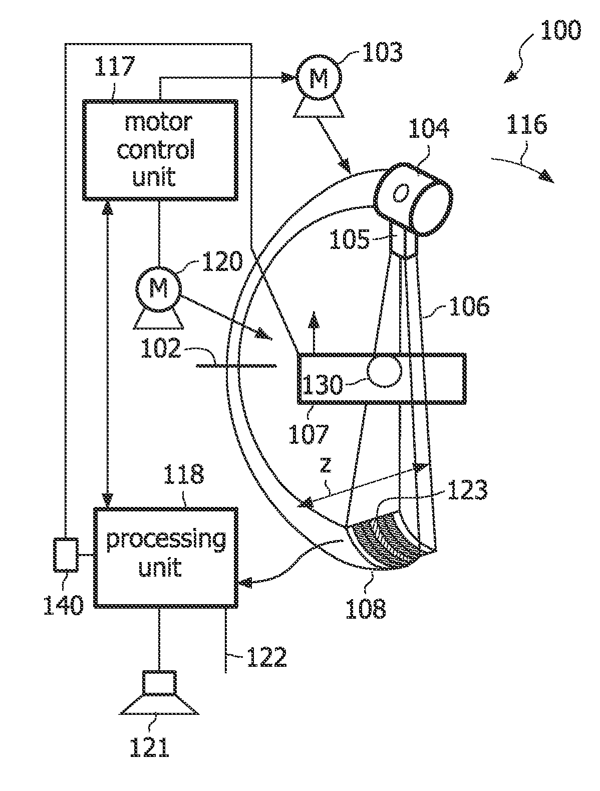
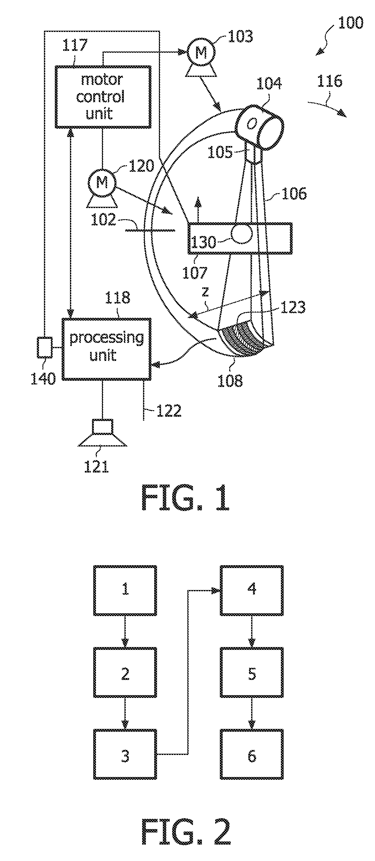
[0025]FIG. 1 shows a schematic representation of a schematic view of a computed tomography C-arm system according to the present invention. The computed tomography apparatus 100 depicted in FIG. 1 is a cone-beam CT C-arm system. The CT C-arm system comprises a C-arm, which is rotatable around a rotational axis 102. The C-arm is driven by means of a motor 103. Reference numeral 104 designates a X-ray tube, which emits polychromatic or monochromatic radiation.

[0026]Reference numeral 105 designates an aperture system which forms the radiation beam emitted from the radiation source 104 to a cone-shaped radiation beam 106. The cone-beam 106 is directed such that it penetrates an object of interest 107 arranged in the centre of the C-arm, i.e. in an examination region of the CT C-arm system, and impinges onto the detector 108....


PUM


Abstract

A Computer Tomography (CT) C-arm system and method for examination of an object is provided. The Computer Tomography (CT) C-arm system for examination of an object of interest, the CT-C-arm system comprises an X-ray tube adapted for generating X-rays, an X-ray detection unit to acquire a set of CT slices, wherein the X-ray tube, and the X-ray detection unit are adapted to be rotatable on a C-arm around a common axis around the object under examination and a processing unit by which the following steps are executable: acquiring a first 3D data volume of the CT slices using first scan parameters; adjusting the first data volume to a second data volume (segmented volume) such that voxel values of the first data volume of at least one predefined range of Hounsfield (H) are set to an at least one predefined H-value; generating a forward projection of the second data volume using the first scan parameters; reconstructing the projection to a third data volume; generating a fourth data volume (artefact-only volume) by subtracting the third volume with the second volume; generating a fifth volume by adding the first volume with the fourth volume.

Description

FIELD OF INVENTION [0001]The invention relates to a Computer Tomography (CT) C-arm system and a method for examination of an object. Further, the invention relates to a computer readable medium and a program element. More particular, the invention relates to a correction of 3D angular underscanning artefacts.TECHNICAL BACKGROUND [0002]Systems for producing an image of a physical object are widespread in several technical fields. One area of particular commercial interest is in the field of CT C-arm systems i.e. C-arm systems which are capable of CT-like 3D imaging. Good 3D image quality requires a C-arm rotation range of at least 180° plus fan angle.[0003]In some medical or other cases it may be desirable to reduce the rotation range of the C-arm. One reason could be that the examination process is faster and therefore more economically. Also, a lower number of examined CT slices due to the reduced rotation range of the object causes less influences of X-rays to the object. Further,...

Claims


Application Information

Patent Timeline
IPC IPC(8): G06K9/00A61B6/03
CPCA61B2560/0242A61B2560/0252G01N23/046G01N2223/419G06T2207/10081G06T2207/30016G06T11/005
Inventor VAN DE HAAR, PETER GEORGE
Owner KONINKLIJKE PHILIPS ELECTRONICS NV
Why Eureka
Try Eureka