Sensor-Equipped Bearing for Wheel

a technology for sensors and bearings, applied in the direction of instruments, force/torque/work measurement apparatuses, transportation and packaging, etc., can solve the problems of sensor fitting member strain, and achieve the effects of reducing the cost of sensor-equipped bearings, ensuring the accuracy of measurement, and convenient installation

Inactive Publication Date: 2010-06-03
NTN CORP
View PDF30 Cites 39 Cited by
  • Summary
  • Abstract
  • Description
  • Claims
  • Application Information

AI Technical Summary

Benefits of technology

[0010]A main object of the present invention is to provide a sensor-equipped bearing for a wheel in which a sensor for detecting a load can be installed compactly in a vehicle, in which a load acting on the wheel can be detected, and in which a cost during the mass production can be reduce. An additional object of the present invention is to provide the sensor-equipped bearing in which the sensor for detecting load can be protected from eroding so as to achieve high reliability, and in which a wiring connecting the sensor and a sensor signal processing circuit can be simplified.

Problems solved by technology

With a load applied to a rotatable member during a vehicle travel, the stationary member is deformed due to the load transmitted thereto via the rolling elements, and the deformation causes a strain of the sensor fitting member.

Method used


Image

  • Sensor-Equipped Bearing for Wheel
  • Sensor-Equipped Bearing for Wheel
  • Sensor-Equipped Bearing for Wheel

Examples


second embodiment

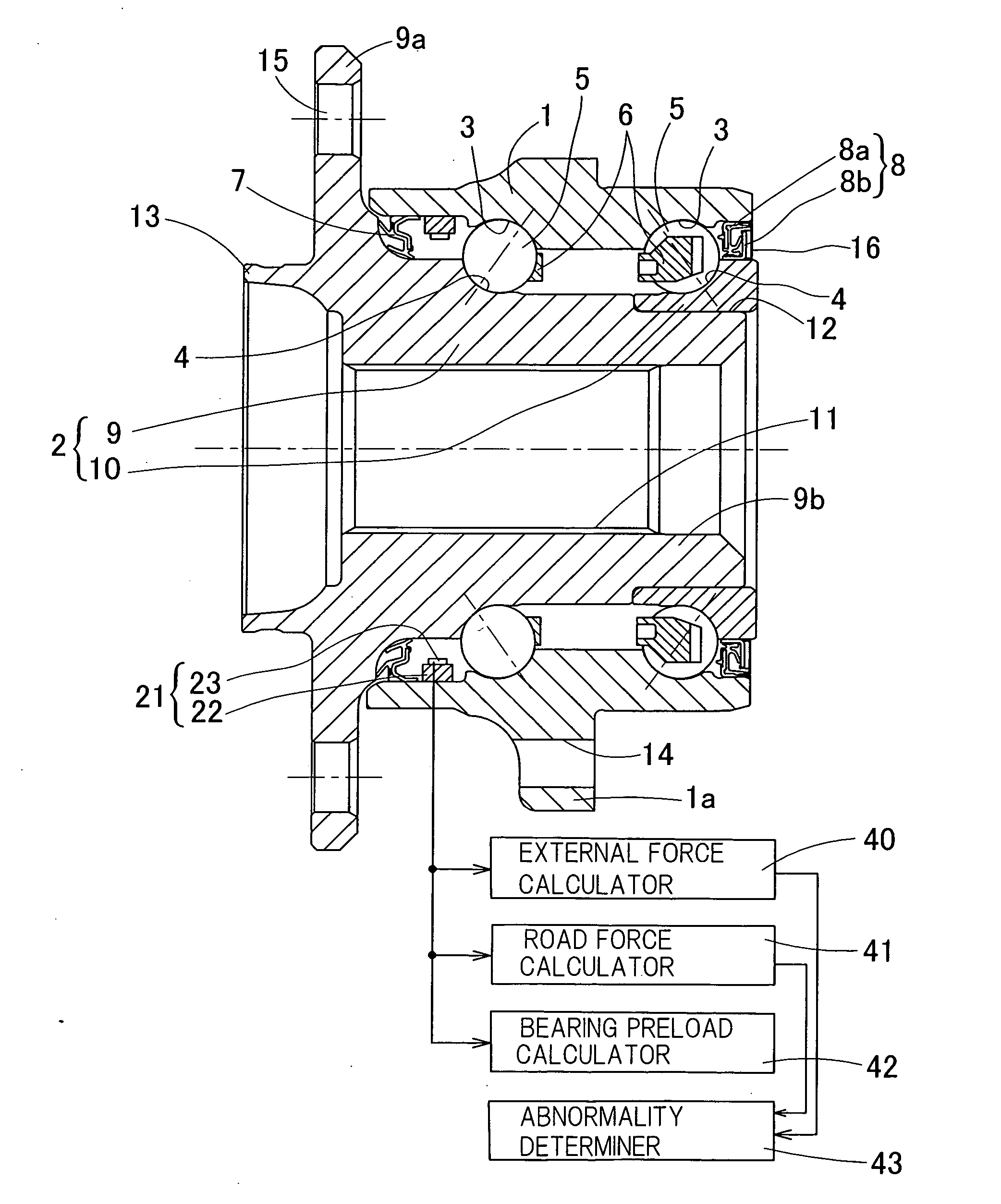
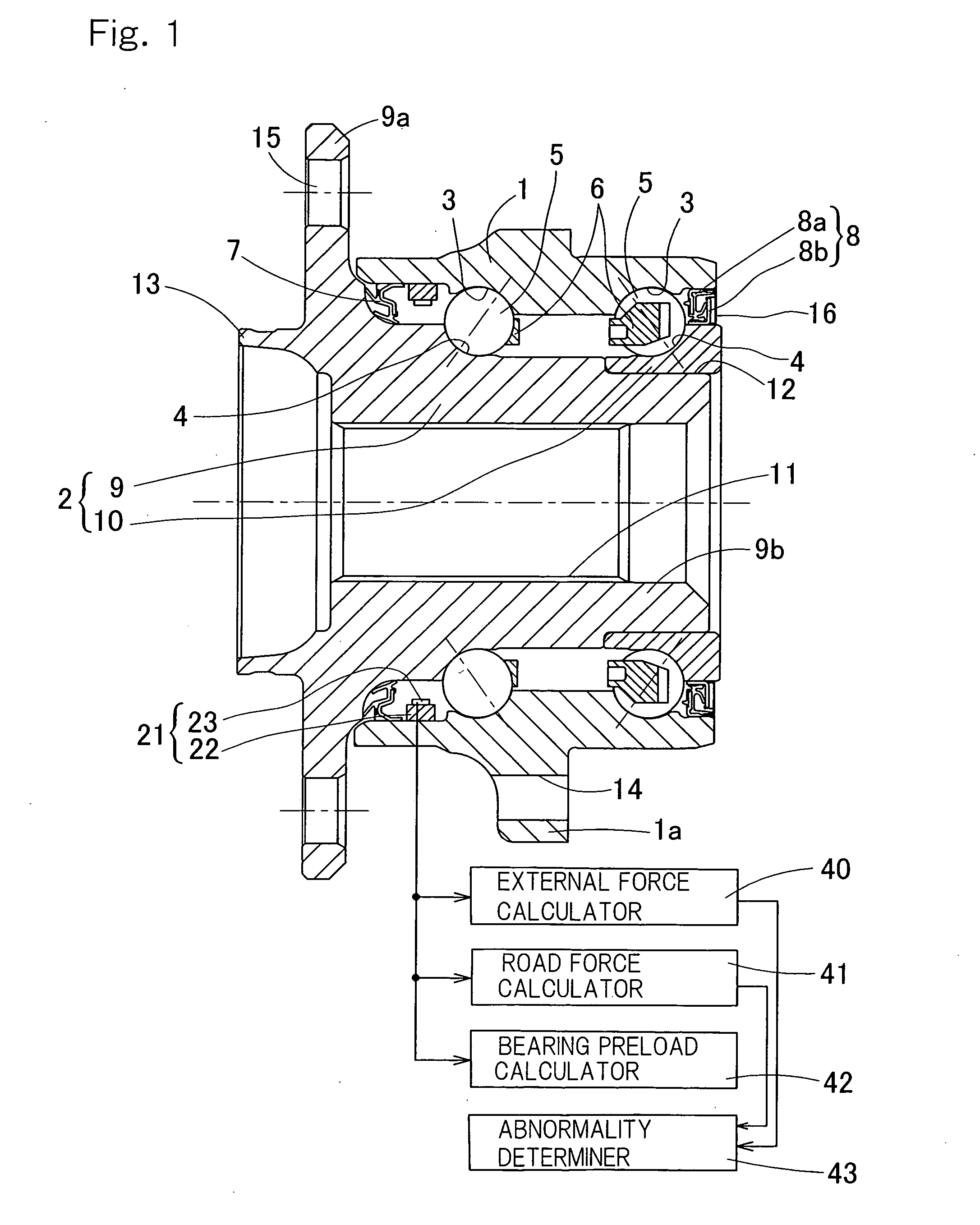
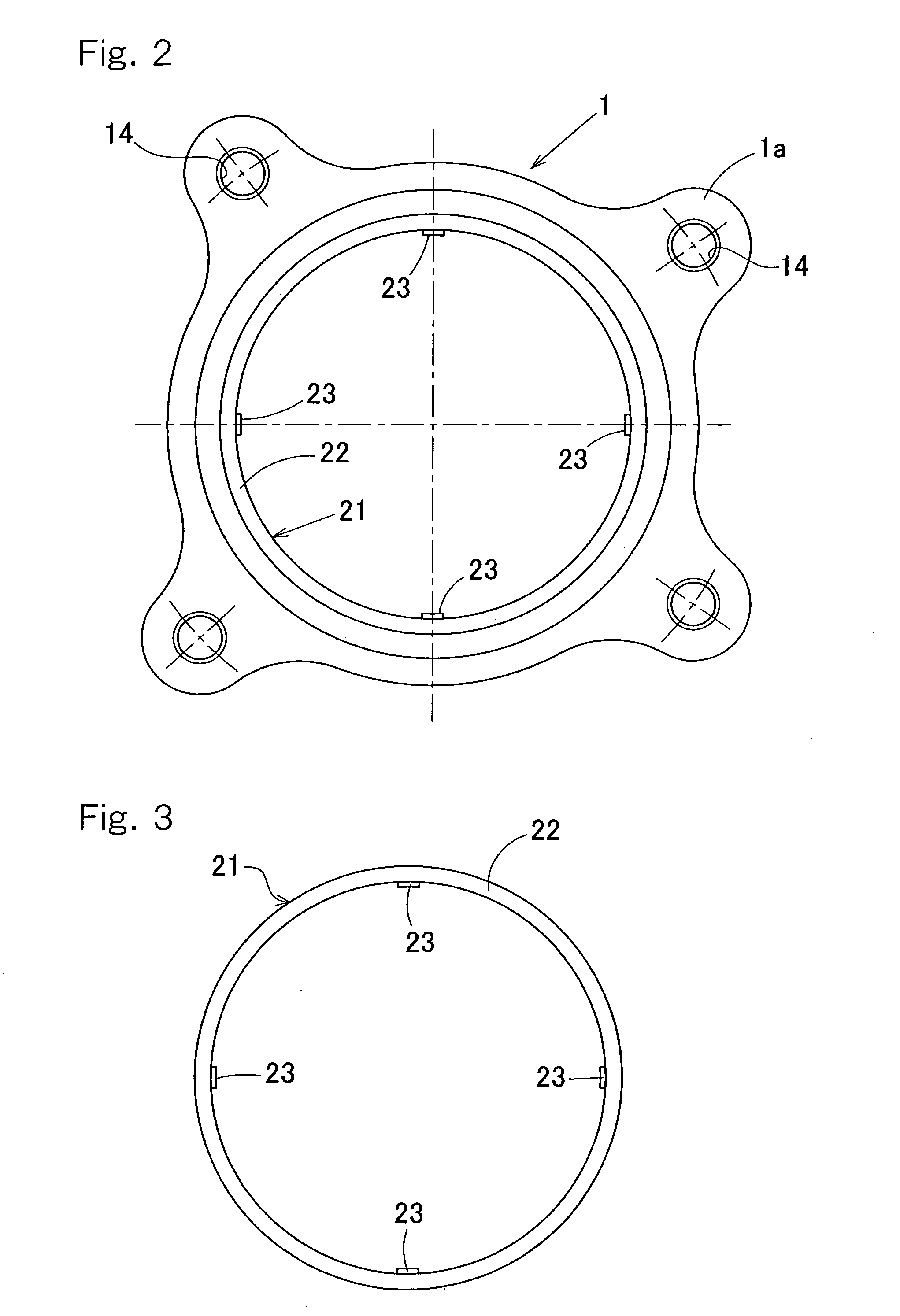
[0113]For the same reason as mentioned above, in order to prevent a gap or a slip from being generated between the sensor fitting member 22 and the inner peripheral surface of the outer member 1, an adhesive agent may be used therebetween. Also, as employed in a second embodiment shown in FIGS. 4 and 5, a bolt 37 may be used for fitting the sensor fitting member 22 to the inner peripheral surface of the outer member 1. In this embodiment, the sensor fitting member 22 is fitted to the outer member 1 by inserting the bolts 37 from a plurality of bolt insertion holes 26 provided in the peripheral surface of the outer member 1, and screwing the bolts 37 into thread holes 27 provided in the sensor fitting member 22.

[0114]In the sensor-equipped bearing for the wheel, since the strain sensor 23 is attached to the sensor fitting member 22 such as the ring-shaped member attached to the inner peripheral surface of the outer member 1 serving as the stationary member, the strain sensor 23 can b...

third embodiment

[0119]In the case of this third embodiment, the first contact fixing portion 22a is fixed to a top position opposite to the road surface in a whole periphery of the outer member 1, and the second contact fixing portion 22b is fixed to a position which is below from the top position by several tens of degrees in the circumferential direction, for example, about 30 degrees to 45 degrees.

[0120]Various types of strain sensors 23 can be used and in this embodiment a metal foil strain gauge is employed, for example. When the metal foil strain gauge is employed, the sensor fitting member 22 is preferably structured such that a strain amount of the strain sensor 23 is equal to or less than 1500 micro strain while taking a durability of the metal foil strain gauge into consideration, when the conceivable maximum load is applied to the bearing. Further, in the case where the strain sensor 23 is constituted by a semiconductor strain gauge is employed, the sensor fitting member 22 is preferably...

sixth embodiment

[0130]Further, although the sensor unit 21 has been described to be provided in the inner periphery of the outer member 1 in each of the embodiments mentioned above, the sensor unit 21 may be provided in the outer periphery of the outer member 1 such as in a sixth embodiment shown in FIGS. 12 and 13.

[0131]A description will be given of a seventh embodiment in accordance with the present invention with reference to FIGS. 14 to 16. In the seventh embodiment shown in FIG. 14, a circumferential groove 20 serving as a weakened portion having a lower rigidity than the surrounding area is formed on the inner periphery of the outboard side end of the outer member 1 at a position between the sealing device 7 and the raceway surface 3 in the axial direction. The sensor unit 21 is disposed at a suitable position in the circumferential groove 20. Since the outboard side end portion of the outer member 1 has no direct effect on the tire support, there is no problem with supporting the tire even ...


PUM


Abstract

A sensor-equipped bearing for a wheel rotatably supporting the wheel relative to a vehicle body includes an outer member (1) provided with a double-row raceway surface (3) on an inner periphery thereof, an inner member (2) provided with raceway surfaces (4) opposing to the raceway surfaces (3) of the outer member (1), one of the outer and inner members serving as a stationary member, double-row rolling elements (5) interposed between the outer and inner raceway surfaces, a sensor fitting member (22) fixed to a peripheral surface of the stationary member, and a plurality of strain sensors (23) attached to the sensor fitting member (22) for measuring a strain thereof.

Description

FIELD OF THE INVENTION[0001]The present invention relates to a sensor-equipped bearing for a wheel having a built-in load sensor to detect a load applied to a bearing portion of a wheel.BACKGROUND OF THE INVENTION[0002]Conventionally, there has been a structure in which a sensor detecting a rotating speed of each of wheels is provided in a bearing, for a safety drive of a motor vehicle. A conventional general countermeasure for securing a traveling safety of the motor vehicle is taken by detecting a rotating speed of the wheel, however, there is demanded to achieve a further control for a safety by using additional sensor signals other than speed sensor signals because only the rotating speed of the wheel is not sufficient.[0003]Accordingly, there can be considered to achieve a posture control based on the load applied to each of the wheels during travel of the vehicle, since the load applied to each of the wheels is not uniform. For example, a great load is applied to the outside w...

Claims


Application Information

Patent Timeline
Patent Type & Authority Applications(United States)
IPC IPC(8): F16C41/00
CPCB60B27/00F16C19/186F16C19/522G01L5/0023G01L5/0019F16C19/52F16C41/00F16C2326/02
Inventor OZAKI, TAKAYOSHIISHIKAWA, TOMOMINISHIKAWA, KENTAROU
Owner NTN CORP
Why Eureka
Try Eureka