Level gauge with positive level verifier

Active Publication Date: 2010-08-19
VEGA AMERICAS
View PDF19 Cites 35 Cited by
  • Summary
  • Abstract
  • Description
  • Claims
  • Application Information

AI Technical Summary

Benefits of technology

[0006]Another aspect is a method of verifying that a high level alarm based on electromagnetic energy reflected from a material in a tank is triggered when the material reaches a high level corresponding to the high level alarm. The method determines a level of the material in the tank by emitting electromagnetic energy towards a surface of the material and measuring the reflected electromagnetic energy received at a detector. A target is provided that may be remotely positioned between the emitter of the electromagnetic energy and the material so that the target r

Problems solved by technology

Both of these methods have drawbacks.
The electronic test which only manipulates the software, does not ensure that the system will function properly since it does not test the measurement device, but rather forces the software to a desired state.
Software manipulations are unacceptable to mos

Method used


Image

  • Level gauge with positive level verifier
  • Level gauge with positive level verifier
  • Level gauge with positive level verifier

Examples


first embodiment

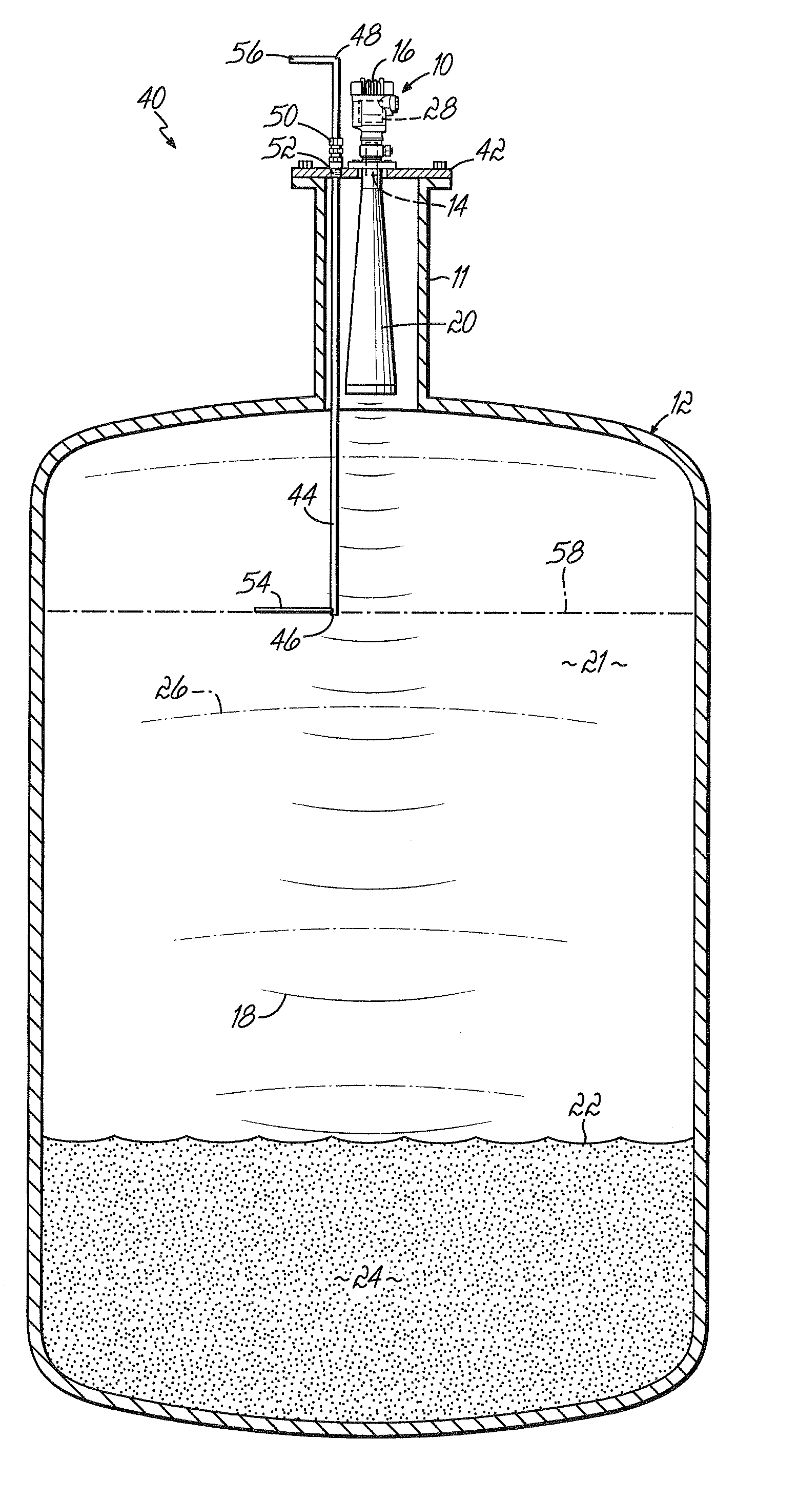
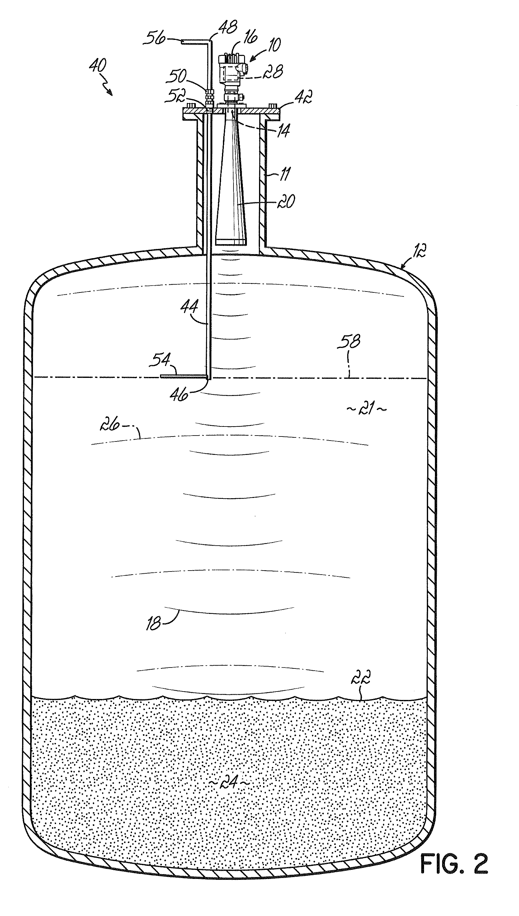
[0018]With reference to FIG. 2, a level verification system 40 is illustrated. The level verification system comprises the radar level gauge 10, a mount plate 42, and a moveable arm 44 having a distal end 46 and a proximal end 48. The movable arm passes through a coupling 50 located in an aperture 52 of the mount plate. A reflective target piece 54 is at the distal end and an indicator 56 at the proximal end. The movable arm may be rotated within the coupling by grabbing the indicator piece, which is strong enough to be a handle. In other embodiments the indicator may be a system other than a handle, such as a dial, or an electronic readout. In some embodiments the movable arm may be extended or retracted in the coupling, moving the target piece closer to or further from the radar level gauge 10. In still other embodiments the movable arm may not be an arm at all, but may be any mechanical or other linkage that can move the target piece between at least two desired positions. The co...

second embodiment

[0027]FIG. 4 illustrates a system 40 with a shortened arm. The target is still in a spacious tank area and able to be sized as large as needed. Typically, because it is closer to the radar level gauge, the target of FIG. 4 would be smaller than a target of FIG. 3, for a given material and safety limit. Or it can be changed in other ways to produce the same signal as a target positioned at the safety limit 58 as in FIG. 3.

third embodiment

[0028]A third embodiment is illustrated in FIGS. 5, 6A-6C and 8. The moving arm is shortened so the target piece rests inside the nozzle. The target has an outside arc edge 60 and an inside arc edge 62 that allow the target to fit in an annulus area 64 defined by the wave guide 20 and inside wall 66 of the nozzle when the target is in its stowed position as shown in FIG. 6A. An advantage of the size and shape shown in FIG. 6A is that the target may be pulled further up towards the mount plate as indicated by arrows 67. This allows out-of-the-way storage, with additional protection as compared to below (FIG. 5) the wave guide. However, if the pulling-up is not desired, the target may be larger and not have a uniform inside arc edge 62 as long as it does not interfere with the microwaves in an amount that interferes with the clear identification of material levels when in the stowed position. For any target, the moveable arm 44 may be used to move the target further away from the rada...


PUM


Abstract

A level verification system for a radar level gauge utilizes a remotely positionable target. The target is positioned inside of a tank that is subject to level measurement, and stowed at a first position and selectively positionable to a second position to reflect emitted electromagnetic radiation in an amount indicative of a predetermined material level. The verification system can verify a high level alarm will be triggered when the material reaches a high level corresponding to the level of the target, by remotely positioning the target in front of the emitter of the radar gauge. The target reflects electromagnetic energy to the detector at approximately the same intensity that the material reaching the high level would reflect so as to provide an accurate verification.

Description

FIELD OF THE INVENTION[0001]The field of the invention is level gauge systems, in particular radar level gauge systems.BACKGROUND OF THE INVENTION[0002]In many environments, various materials are stored or processed in tanks. These materials include foods, beverages, pharmaceuticals and fuels. Non-contact level sensing gauges are used for such environments. There are several types. Examples include those that use radar transmitters, or ultrasonic waves. A high degree of accuracy has been achieved by the use of level-sensing gauges which monitor content levels by transmitting microwave pulses from an antenna toward the surface of the tank contents. These pulses are reflected from the contents and back to the antenna. Other radar gauges use a frequency modulated continuous wave rather than pulses.[0003]Radar signals are largely unaffected by noise, by air turbulence, or by fluctuations in dielectric constant above a nominal minimum value, density, or conductivity. Even liquids having ...

Claims


Application Information

Patent Timeline
IPC IPC(8): G01S13/08
CPCG01F25/0061G01F23/284G01F25/20
Inventor KUHLOW, KYLELONGCOR, CRAIG
Owner VEGA AMERICAS
Why Eureka
Try Eureka