Hydraulic supply hose including an integral tensile load member

Active Publication Date: 2010-09-23
DANFOSS POWER SOLUTIONS II TECH AS
View PDF18 Cites 9 Cited by
  • Summary
  • Abstract
  • Description
  • Claims
  • Application Information

AI Technical Summary

Benefits of technology

[0006]By providing a supply hose with significant strength, the supply hose may be able to significantly support the weight of a pump within a well. Not only will the supply hose be able to support the weight of the pump, but the hose is a

Problems solved by technology

Attaching and detaching the individual lengths of pipe together to positi

Method used


Image

  • Hydraulic supply hose including an integral tensile load member
  • Hydraulic supply hose including an integral tensile load member
  • Hydraulic supply hose including an integral tensile load member

Examples


Example

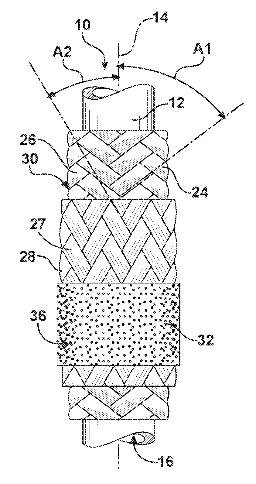
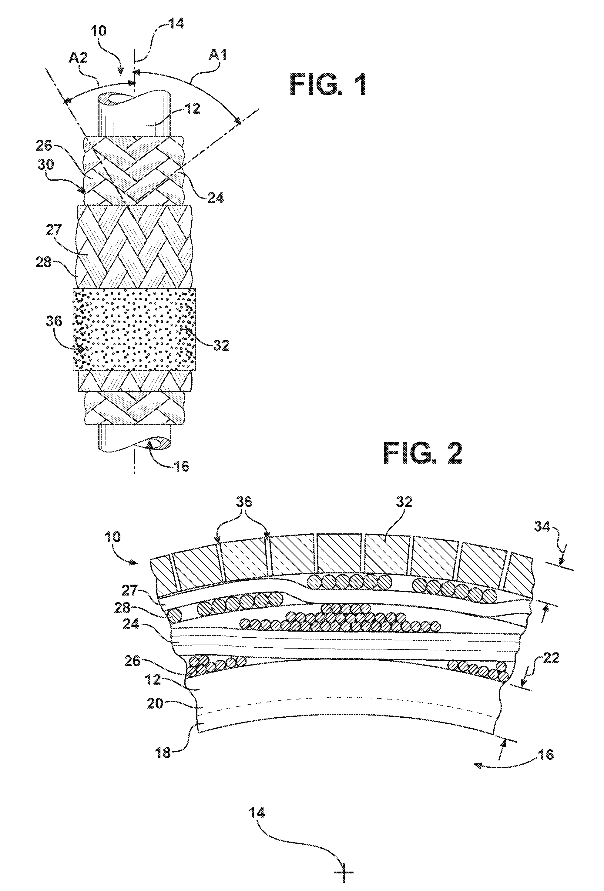
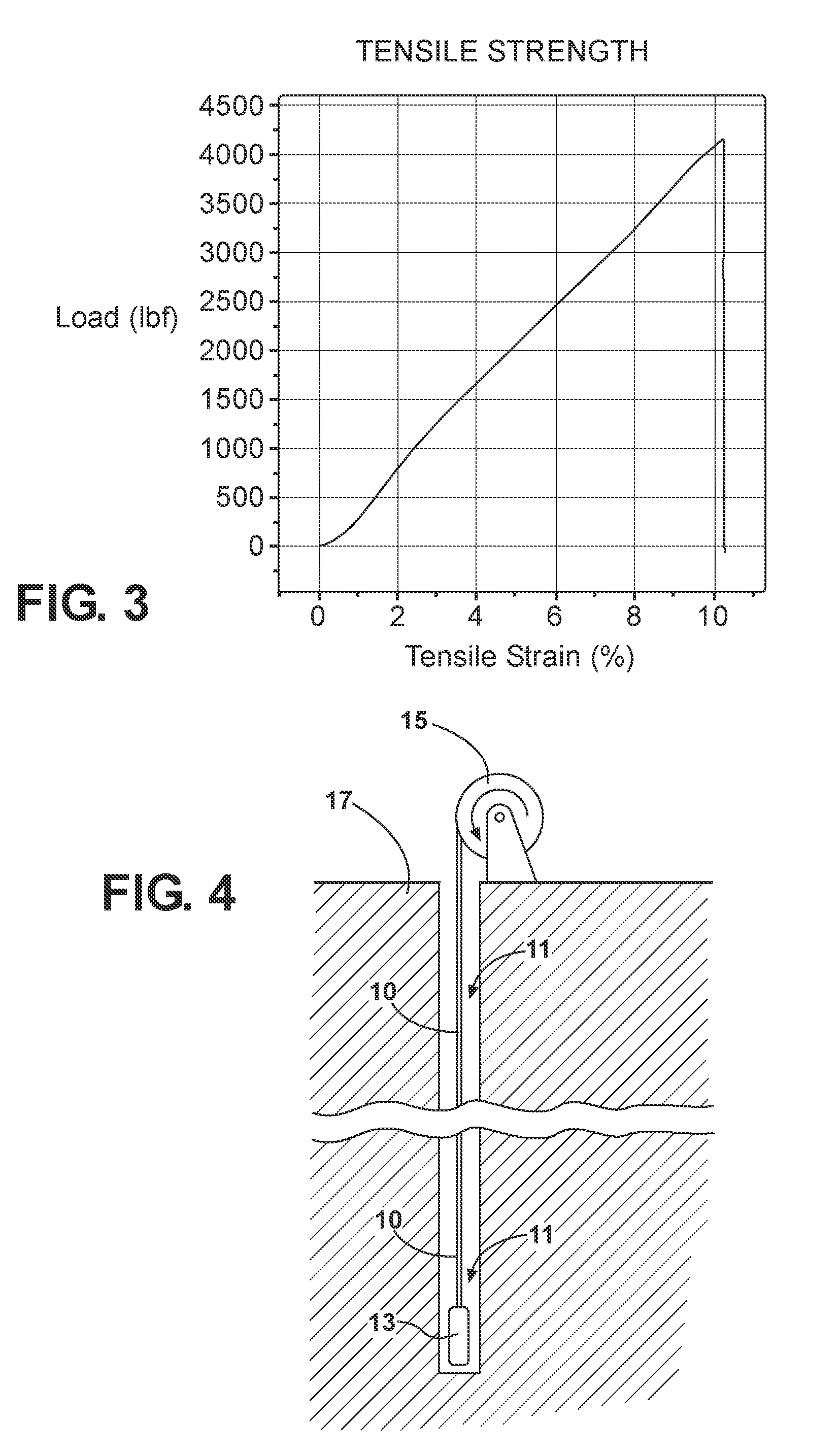
[0013]Referring to the drawings, wherein like reference numbers refer to like components, FIG. 1 shows a hydraulic supply hose at 10. The hose may be used to transport fluid to a down-hole well 11 via a submersible pump 13, as illustrated in FIG. 4. The well 11 may be dug into the ground 17. The supply hose 10 may be attached to the pump and lowered into the well 11, as shown in FIG. 4. The supply hose 10 may be wound around a hose reel 15 and unrolled to lower the pump 13 into the well 11. The supply hose 10 is configured such that the weight of the pump 13 is substantially supported by the supply hose 10. For example, if the well 11 has a depth of 2,000 feet (i.e., 609.6 meters), the supply hose 10 supports the weight of the pump 13. This means that the supply hose 10 substantially supports the weight of the pump 13, the length of the supply hose 10, and any fluid contained therein at the depth of 2,000 feet. Therefore, supply hose 10 is configured to have sufficient tensile stren...


PUM

PropertyMeasurementUnit
Lengthaaaaaaaaaa
Fractionaaaaaaaaaa
Linear densityaaaaaaaaaa

Abstract

A supply hose includes a core tube, a first layer, a second layer, and a sheath. The core tube defines a hollow interior that surrounds a central axis and is configured to transport fluid therethrough. The first layer and/or the second layer provide tensile strength to the supply line. The first layer is disposed about the core tube and includes a plurality of first fibers. The first fibers are braided about the core tube at a first angle, relative to the central axis. The second layer is disposed directly on the exterior surface of the first layer and includes a plurality of second fibers. The second fibers are braided about the exterior surface of the first layer at a second angle, relative to the central axis. The sheath may be disposed about the second layer.

Description

TECHNICAL FIELD[0001]The present invention relates to a hydraulic supply hose including an integral tensile load member.BACKGROUND OF THE INVENTION[0002]A pump is typically connected to a length of pipe and inserted down into a well. The length of pipe may be formed from a plurality of individual smaller lengths of pipe that are attached to one another as the pump is lowered down into the well. In addition, the weight of the pump may be supported by the pipe. For example, a length of pipe that is approximately 2,000 feet long may be attached to the pump that is disposed approximately 2,000 feet down in the well. To achieve the 2,000 foot length of pipe, an individual smaller length of pipe is attached to the pump and lowered down into the well. Next, another individual small length of pipe is attached to the first length of pipe so that the pump can be lowered a little further down into the well. This process continues until the desired depth of 2,000 feet is achieved. Likewise, to ...

Claims


Application Information

Patent Timeline
IPC IPC(8): F16L11/04E21B23/00
CPCF16L11/086Y10T29/49826F16L11/02B23P19/00F16L11/085
Inventor GREGRICH, GLENN M.MANAS, IANISIMMONS, CHARLES T.
Owner DANFOSS POWER SOLUTIONS II TECH AS
Why Eureka
Try Eureka