Beaded thin wall large aerosol container

Inactive Publication Date: 2007-06-05
BALL METALPACK AEROSOL CONTAINER LLC
View PDF6 Cites 2 Cited by
  • Summary
  • Abstract
  • Description
  • Claims
  • Application Information

AI Technical Summary

Benefits of technology

[0009]Among the objects of the invention, briefly stated, is a thin wall aerosol container for use in dispensing a fluent material. The container is either of a 2-piece or 3-piece construction, and is either a barrier or non-barrier type container. The container includes a cylindrical can body having a beaded construction. The beading adds significant structural strength to the container and prevents distortion or crushing of the container sidewall when the can is un-pressurized. The container also includes a spray valve

Problems solved by technology

Additionally, the can, when empty, is said to be easily crushable by hand pressure.
However, the cans cannot be vacuum filled at a vacuum level greater than 18 inches of Mercury because if they are, the container will collapse.
While there are a number of advantages to a container having thin sidewalls (lower material costs, for example), current thin wall can constructions have drawbacks as well.
For example, during handling of the container prior to its being filled, even a

Method used


Image

  • Beaded thin wall large aerosol container
  • Beaded thin wall large aerosol container
  • Beaded thin wall large aerosol container

Examples


Embodiment Construction

[0018]The following detailed description illustrates the invention by way of example and not by way of limitation. This description will clearly enable one skilled in the art to make and use the invention, and describes several embodiments, adaptations, variations, alternatives and uses of the invention, including what I presently believe is the best mode of carrying out the invention. As various changes could be made in the above constructions without departing from the scope of the invention, it is intended that all matter contained in the above description or shown in the accompanying drawings shall be interpreted as illustrative and not in a limiting sense.

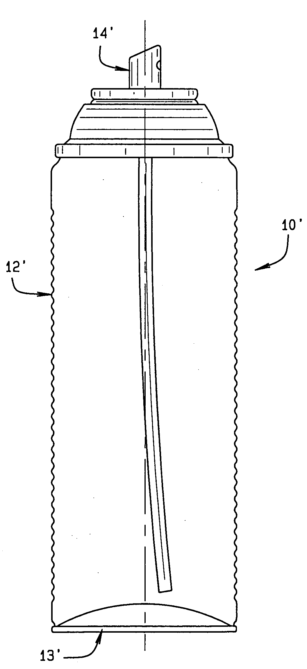
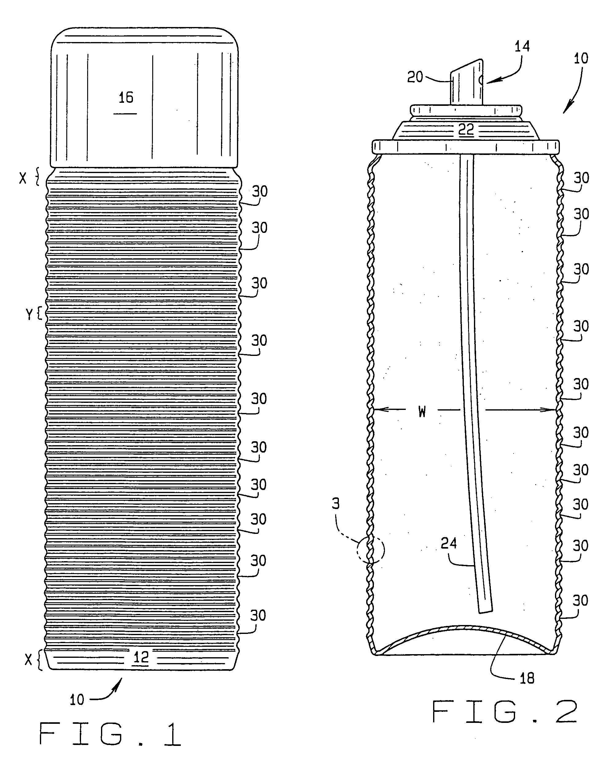
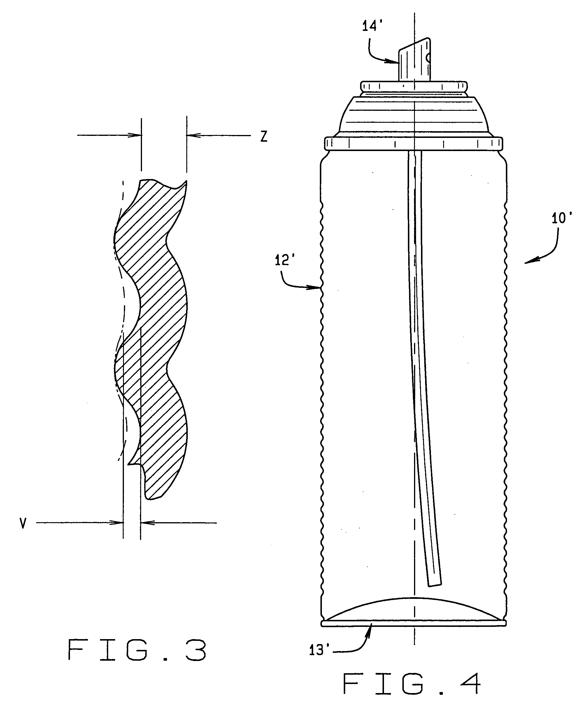
[0019]Referring to the drawings, an aerosol container of the present invention is indicated generally 10 in FIGS. 1 and 2. In FIG. 2, the container is shown to be a non-barrier type container (that is, it has no wall separating the fluent material discharged from the container with a propellant used for this purpose); although...


PUM


Abstract

A large size aerosol container (10′) dispensing a fluent material. A generally cylindrical can body (12′) is fabricated from a steel sheet and has a relatively thin sidewall thickness of between 0.004 inches and 0.010 inches depending upon the weight of the steel sheet from which the container is made. The can body has beads (30) formed at regular intervals substantially its length. The beading adds structural strength to the container so the container is not damaged by handling during manufacture of the container, will not collapse during vacuum filling, and cannot be crushed by hand before the container is filled. The container can withstand a vacuum of at least 23 inches of Mercury without collapsing. A valve assembly (14′) includes a spray valve (20) for dispensing the fluent material stored in the container. The container is filled with the fluent material and a propellant stored in the container under pressure.

Description

CROSS REFERENCE TO RELATED APPLICATIONS[0001]This application is a continuation-in-part of U.S. patent application Ser. No. 10 / 238,286, filed Sep. 10, 2002 now U.S. Pat. No. 6,786,370.STATEMENT REGARDING FEDERALLY SPONSORED RESEARCH OR DEVELOPMENT[0002]Not applicableBACKGROUND OF THE INVENTION[0003]This invention relates to aerosol containers, and more particularly to a 2 piece or 3 piece thin walled, non-barrier type aerosol container.[0004]Thin wall, non-barrier type, aerosol containers are known in the art. See, for example, U.S. Pat. No. 5,211,317 to Diamond et al., and its reissue Re 35,843. It is a feature of containers built in accordance with the teachings of these patents that the sidewall of the container has a relatively thin thickness. In the Diamond et al. patent and its reissue, the container wall thickness is said to be on the order of 0.004-0.005 inches (0.102 mm-0.127 mm).[0005]In un-pressurized containers, it is often possible to distort the sidewall of the contain...

Claims


Application Information

Patent Timeline
IPC IPC(8): B65D83/14B65D83/00B65D83/38
CPCB65D83/38
Inventor KUBACKI, EDWARD F.
Owner BALL METALPACK AEROSOL CONTAINER LLC
Why Eureka
Try Eureka