
Continuous Annealing and Hot Dip Plating Method and Continuous Annealing and Hot Dip Plating System of Steel sheet Containing Si

Inactive Publication Date: 2009-05-14
NIPPON STEEL & SUMITOMO METAL CORP
View PDF21 Cites 61 Cited by
  • Summary
  • Abstract
  • Description
  • Claims
  • Application Information

AI Technical Summary

Benefits of technology

[0011]Therefore, an object of the present invention is to provide a system and method for hot dip plating steel sheet containing Si by an indirect heating system during which preventing the formation of surface oxides of the iron metal in the relatively low temperature range and causing the Si or Mn to internally oxidize and thereby avoid a drop in the plating ability of the steel sheet and retardation in alloying.
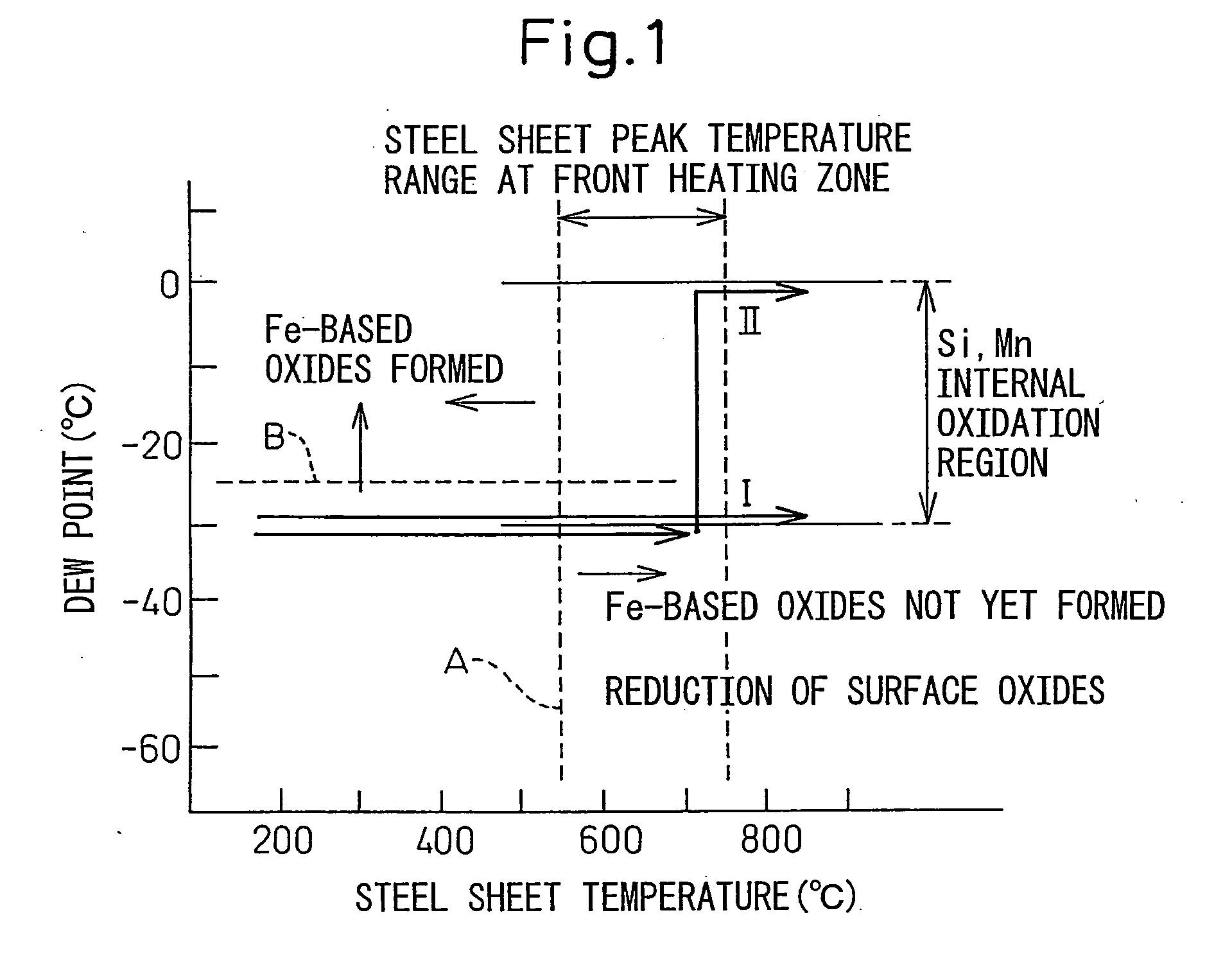
[0021]According to the present invention, when heating steel sheet containing Si, the dew points of the heating zone and soaking zone are controlled to avoid the formation of Fe-based oxides at the steel sheet surface and the Si is made to internally oxidize so suppress the surface concentration of Si. Production of hot dip plated steel sheet superior in plating appearance and plating adhesion and production of alloyed hot dip plated steel sheet not requiring an extreme rise in the alloying temperature or a longer alloying time become possible.

Problems solved by technology

With this method, when the components of the steel sheet include Si, Mn, and other easily oxidizable metals, during the annealing, these easily oxidizable elements form single or composite oxides at the steel sheet surface, obstruct the plating ability, and cause nonplating defects.
Therefore, this is particularly a problem.
To avoid this problem, it is sufficient to sharply lower the oxygen potential in the annealing atmosphere, but industrially obtaining an atmosphere in which Si, Mn, etc. will not oxidize is de facto impossible.
However, these prior arts have the following problems.
If the oxide films are insufficiently reduced, conversely a drop in the plating ability is induced.
Therefore, extremely sophisticated control of the furnace operation is necessary, so these methods lack industrial stability.
Further, oxide films formed by a direct-fired heating furnace will peel off from the steel sheet and deposit on the roll surfaces while the steel sheet is being wound around the rolls in the furnace, so will form impression defects in the steel sheet.
This technology cannot be used for an indirect heating hot dip plating system.
Japanese Unexamined Patent Publication No. 2000-309824 disclose the method of heat treating the steel sheet at the hot rolled stage to cause the harmful Si, Mn, etc. to internally oxidize and render them harmless, but the number of steps increases compared with the usual process of production of hot dip plated steel sheet, so the production costs unavoidably rise.
However, the atmospheric conditions in an annealing furnace for causing Si or Mn to internally oxidize are also the conditions where surface oxidation of the iron metal occurs in the relatively low steel sheet temperature region, so unless defining the method of adjustment of the atmosphere in the annealing furnace, hearth roll defects are liable to be caused by the iron metal surface oxide film formed at the low temperature range.

Method used


Image

  • Continuous Annealing and Hot Dip Plating Method and Continuous Annealing and Hot Dip Plating System of Steel sheet Containing Si
  • Continuous Annealing and Hot Dip Plating Method and Continuous Annealing and Hot Dip Plating System of Steel sheet Containing Si

Examples


examples

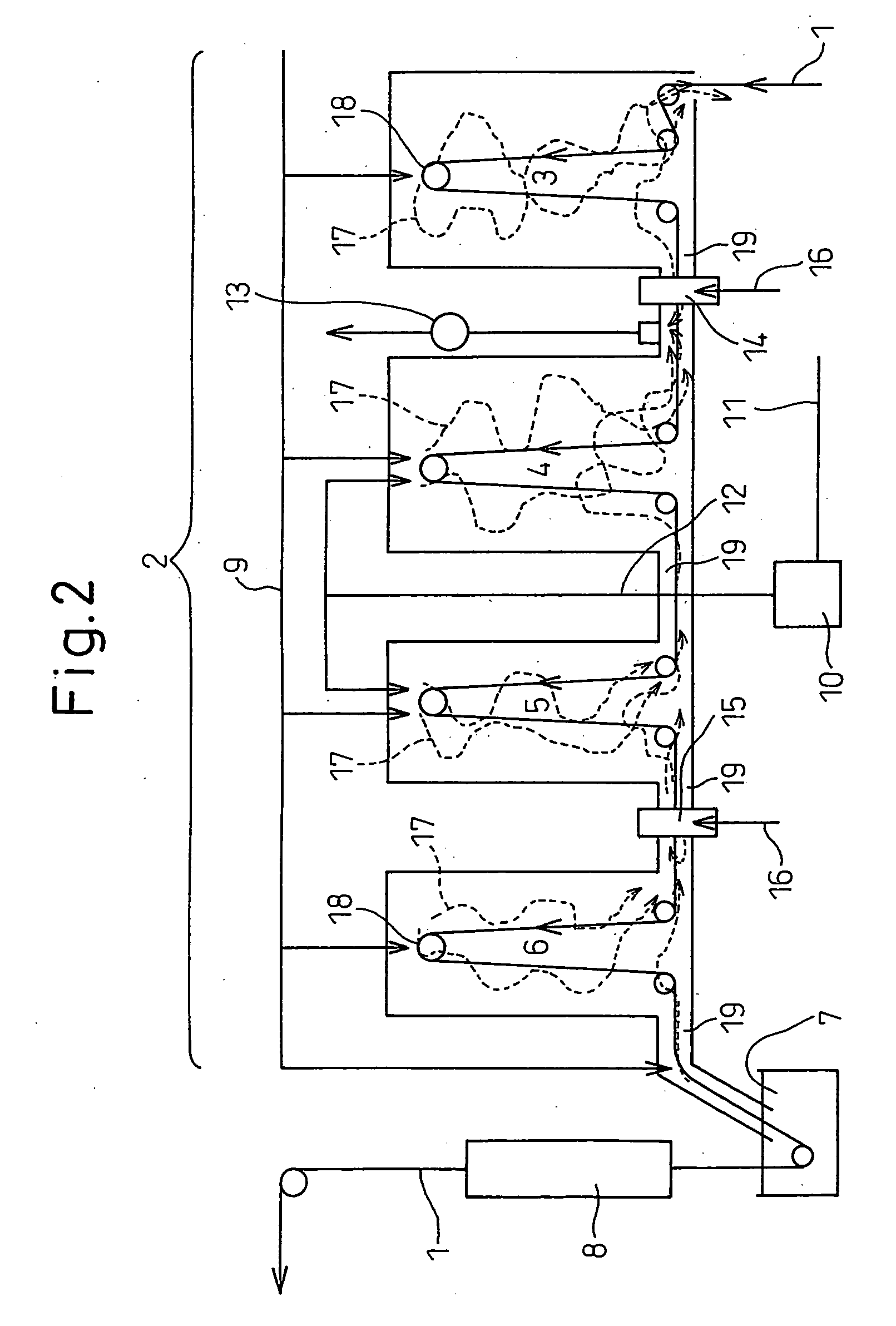
[0038]FIG. 2 shows an outline of one embodiment of a hot dip plating system of the present invention. In the present embodiment, the hot dip plating system is comprised of, in order in the conveyance direction of the steel sheet 1, an annealing furnace 2 having a front heating zone 3, a rear heating zone 4, a soaking zone 5, and a cooling zone 6, a hot dip plating bath 7, and an alloying system 8. The zones 3, 4, 5, and 6 of the annealing furnace are provided with rollers 18 for continuously conveying the steel sheet. Openings 19 are provided between the zones to enable the steel sheet to pass through the zones in the furnace. The zones in the annealing furnace 2 are connected to atmospheric gas pipes 9 for introducing atmospheric gas comprised of hydrogen and nitrogen. Wet nitrogen is obtained by blowing into nitrogen gas from a nitrogen pipe 11 to a nitrogen wetting system 10 and travels through a wet nitrogen feed pipe 12 to be introduced to the rear heating zone 4 and soaking zo...


PUM

PropertyMeasurementUnit
Temperatureaaaaaaaaaa

Abstract

The present invention provides, in a hot dip plating system having an annealing furnace for hot dip plating steel sheet containing Si, a continuous annealing and hot dip plating method and system causing internal oxidation without causing surface oxidation of the Si in the steel and avoiding a drop in the plating ability of the steel sheet and retardation of alloying, that is, a continuous annealing and hot dip plating method using an annealing furnace having, in order, a front heating zone, rear heating zone, soaking zone, and cooling zone and a hot dip plating bath, comprising heating or soaking the steel sheet at a steel sheet temperature of a temperature range of at least 300° C. or more by indirect heating, making an atmosphere of the zones one comprised of hydrogen H: 1 to 10 vol % and a balance of nitrogen and unavoidable impurities, making a steel sheet peak temperature during heating at the front heating zone 550 to 750° C. and making the dew point less than −25° C., making dew points of the following rear heating zone and soaking zone −30° C. to 0° C., and making a dew point of the cooling zone less than −25° C.

Description

TECHNICAL FIELD[0001]The present invention relates to a continuous annealing and hot dip plating method and continuous annealing and hot dip plating system for steel sheet containing Si.[0002]Note that the hot dip plating in the present invention does not particularly specify the type of the plating metal and includes hot dip plating of zinc, aluminum, tin, or other metals and their alloys.BACKGROUND ART[0003]When hot dip plating steel sheet with zinc, aluminum, tin, or another metal or their alloys, usually the surface of the steel sheet surface is degreased and cleaned, then the steel sheet is annealed by an annealing furnace, the steel sheet surface is activated by hydrogen reduction, the sheet is cooled to a predetermined temperature, then the sheet is dipped in a hot dip plating bath. With this method, when the components of the steel sheet include Si, Mn, and other easily oxidizable metals, during the annealing, these easily oxidizable elements form single or composite oxides ...

Claims


Application Information

Patent Timeline
IPC IPC(8): B05D1/18B05C11/00
CPCC23C2/28C23C2/02C23C2/06C21D1/76C21D9/561C21D9/573C21D9/563C21D9/565C21D1/52C22C38/02C23C2/0222C23C2/0224C23C2/004C23C2/40C21D1/26
Inventor OKADA, NOBUYOSHI
Owner NIPPON STEEL & SUMITOMO METAL CORP
Learn More