Image display apparatus

a technology of image display and backlight luminance, which is applied in the direction of instruments, computing, electric digital data processing, etc., can solve the problems of deteriorating image quality, affecting the image quality, and the control of backlight luminance may not cope with the video image having the display image luminance, so as to suppress the deterioration of image quality and reduce the power consumption of backligh

Active Publication Date: 2010-11-25
MAXELL HLDG LTD
View PDF6 Cites 40 Cited by
  • Summary
  • Abstract
  • Description
  • Claims
  • Application Information

AI Technical Summary

Benefits of technology

[0016]The present invention makes it possible to reduce the backlight power consumption while suppressing deterioration of the image quality irrespective of sharp change in the luminance of the display image.

Problems solved by technology

In the case where the rate for changing the backlight luminance along the time axis is retarded over several frames, the control for changing the backlight luminance may fail to cope with the video image having the display image luminance sharply changed.
As a result, the brightness of the display screen unnaturally changes, thus deteriorating image quality.

Method used


Image

  • Image display apparatus
  • Image display apparatus
  • Image display apparatus

Examples


first embodiment

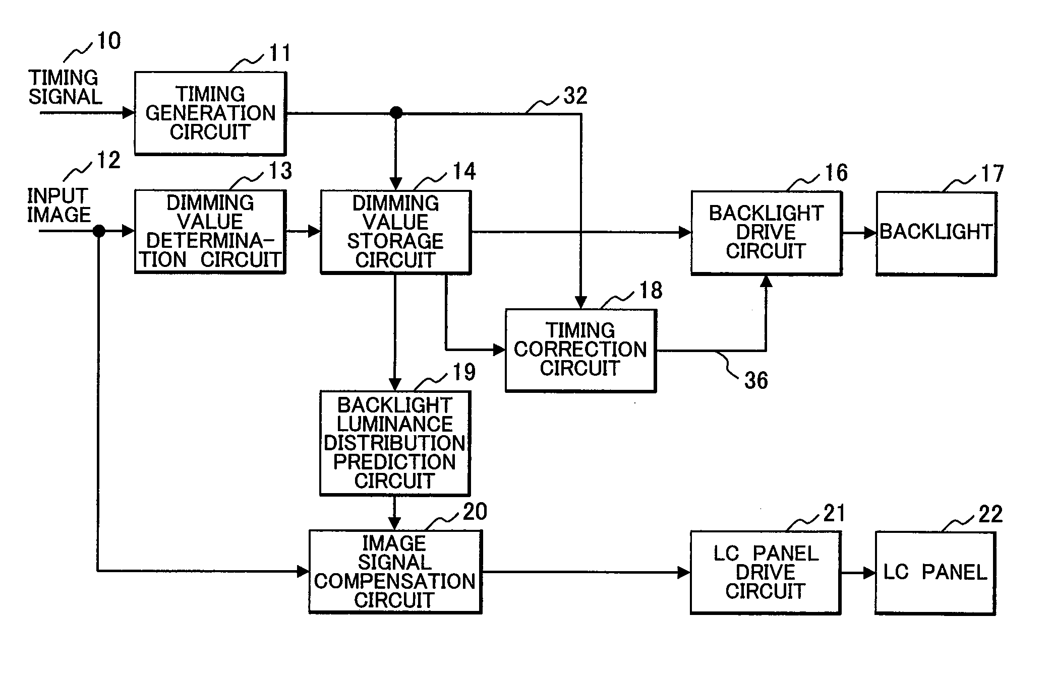
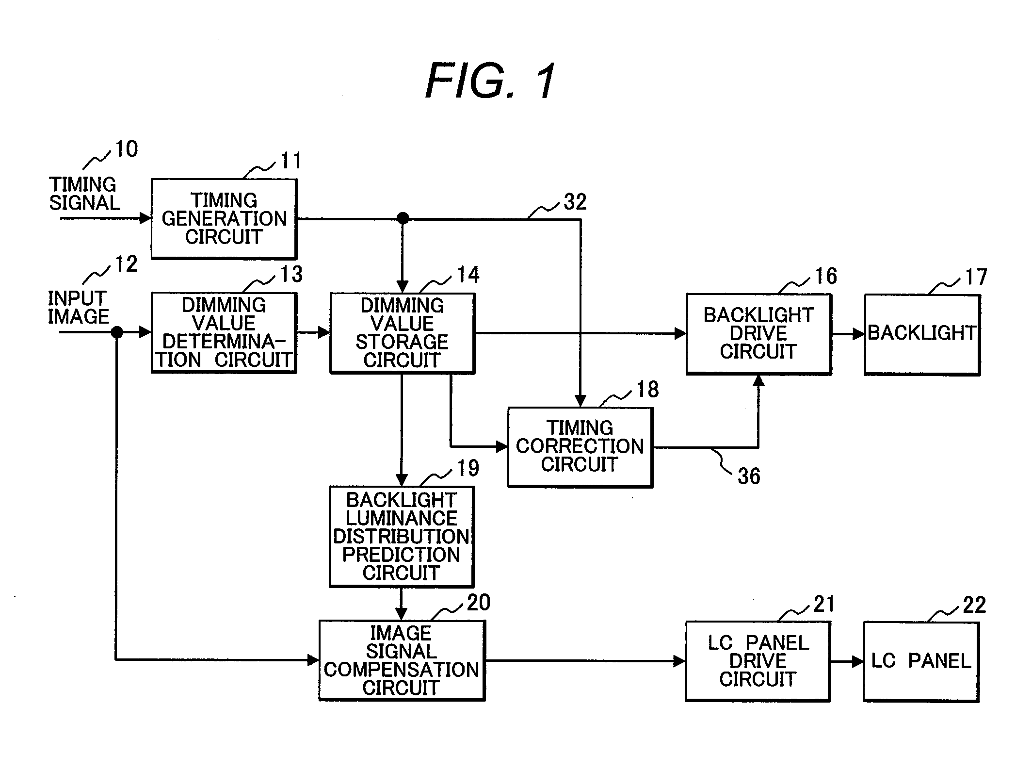
[0058]FIG. 1 is a block diagram illustrating an image display apparatus according to a first embodiment of the present invention.

[0059]An input image 12 to be displayed and a timing signal 10 indicating timing information of the input image 12 are input to the apparatus. Dot clocks and synchronous signals correspond to the timing signal 10. A timing generation circuit 11 generates various timing signals such as clock, address, and trigger signal based on the input timing signal 10 so as to be supplied to the respective circuits in the apparatus. Those timing signals are only partially described for avoiding the complexity drawing.

[0060]A dimming value determination circuit 13 analyzes the input image 12 which has been input, and determines a light emission amount (hereinafter referred to as a dimming value) of each of the light sources for forming a backlight 17. The light emission amount of the light source is determined based on the pixel value with the maximum luminance among tho...

second embodiment

[0094]In a second embodiment, the value of the delay time Tx is fixed to the time corresponding to the single frame. In this case, the backlight luminance (dimming value) of the previous frame may be continuously used for the present frame to establish the delay time Tx for the single frame so as to omit the delay circuit.

[0095]FIG. 8 is a block diagram representing the image display apparatus according to the second embodiment of the present invention. Referring to the drawing, a dimming value change determination circuit 40 determines with respect to the trend of change in the dimming value along the time axis for each region. A dimming value selection circuit 41 selects the dimming value to be used based on the determination result from the dimming value change determination circuit 40. Structures of other circuits are the same as those described in the first embodiment (FIG. 1).

[0096]FIG. 9 illustrates an example of inner structures of the dimming value change determination circ...

third embodiment

[0099]In a third embodiment, the backlight luminance (dimming value) is changed by setting an intermediate level without changing at a time. That is, in the single frame period at the switching point, the intermediate value (correction value) obtained from the backlight luminance values before / after the switching is set to reduce fluctuation of the display luminance.

[0100]FIG. 11 is a block diagram illustrating an image display apparatus according to a third embodiment of the present invention. Referring to the drawing, a dimming value change determination circuit 50 determines a change amount of the dimming value for each region, and outputs correction coefficients C and (1−C). A dimming value correction circuit 51 uses the correction coefficients C and (1−C) to determine the correction value. Structures of the other circuits are the same as those described in the first embodiment (FIG. 1).

[0101]FIG. 12 illustrates an example of inner structures of the dimming value change determin...


PUM


Abstract

An image display apparatus includes a dimming value determination circuit for determining a dimming value of a backlight based on an input image signal, an image signal compensation circuit for compensating the input image signal supplied to a liquid crystal panel in accordance with the dimming value, and a backlight drive circuit for driving and controlling the backlight in accordance with the dimming value. When the light emitting luminance of the present frame of the backlight increases relative to the light emitting luminance of the previous frame, the backlight drive circuit delays the timing for applying the dimming value of the present frame. This makes it possible to reduce power consumption of the backlight by suppressing deterioration in the image quality in spite of the sharp change in the display image luminance.

Description

CLAIM OF PRIORITY[0001]The present application claims priority from Japanese patent application serial No. JP 2009-120969, filed on May 19, 2009, the content of which is hereby incorporated by reference into this application.BACKGROUND OF THE INVENTION[0002](1) Field of the Invention[0003]The present invention relates to an image display apparatus which uses a light source unit to display an input image on a display panel.[0004](2) Description of the Related Art[0005]In the case where the display device such as a liquid crystal display panel uses a backlight as the light source (light source unit) instead of emitting light by itself, the power consumption of the backlight occupies a major part of that of the display device. Reduction of the backlight power consumption is effective for reducing the entire power consumption of the display device. For example, amount of light from the backlight is reduced when displaying a dark image on the screen so as to reduce the power consumption....

Claims


Application Information

Patent Timeline
Patent Type & Authority Applications(United States)
IPC IPC(8): G09G5/10
CPCG09G3/3426G09G2320/0238G09G2320/0247G02F2001/133601G09G2330/021G02F1/1336G09G2320/0646G02F1/133601
Inventor TANAKA, KAZUHIKOTSURU, YASUTAKAOGI, YUYA
Owner MAXELL HLDG LTD
Why Eureka
Try Eureka