A liquid crystal display panel and its driving device and method

A technology of a liquid crystal display panel and a driving method, which is applied to static indicators, instruments, etc., can solve the problem of low effective utilization of backlight, and achieve the effects of increasing color performance, colorful pictures, and preventing liquid crystal aging.

Inactive Publication Date: 2015-09-09
BEIJING BOE OPTOELECTRONCIS TECH CO LTD
View PDF4 Cites 0 Cited by
  • Summary
  • Abstract
  • Description
  • Claims
  • Application Information

AI Technical Summary

Problems solved by technology

However, due to the scattering and refraction of CF, the effective utilization of backlight is still not high.

Method used


Image

  • A liquid crystal display panel and its driving device and method
  • A liquid crystal display panel and its driving device and method
  • A liquid crystal display panel and its driving device and method

Examples


Embodiment Construction

[0069] The basic idea of ​​the present invention is: when the signal type of the received drive signal is not an RGBWY drive signal, decompose the drive signal; output the decomposed drive signal according to the pixel array structure of the liquid crystal display panel; When the signal type of the drive signal received is an RGBWY drive signal, the drive signal is output directly according to the pixel array structure of the liquid crystal display panel; wherein, the RGBWY drive signal includes a red component, a green component, a blue component, and a white component and the drive signal for the yellow component.

[0070] In order to make the object, technical solution and advantages of the present invention clearer, the present invention will be further described in detail by citing the following embodiments and referring to the accompanying drawings.

[0071] Figure 5 Shows the implementation flow of the liquid crystal display panel driving method of the present inventi...


PUM


Abstract

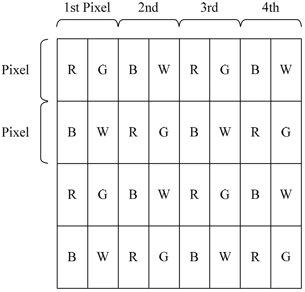
A liquid crystal display panel, and a driving device and a method thereof. The method comprises: when a signal type of a received driving signal is not an RGBWY driving signal, decomposing the driving signal (501); outputting the decomposed driving signal according to a pixel array structure of the liquid crystal display panel (502); and when the signal type of the received driving signal is the RGBWY driving signal, directly outputting the driving signal according to the pixel array structure of the liquid crystal display panel (503). The liquid crystal display panel increases backlight utilization by adding white sub-pixels, improves color expression ability by adding yellow sub-pixels, and increases mix-color effects by using a pixel array of a pentile matrix structure.

Description

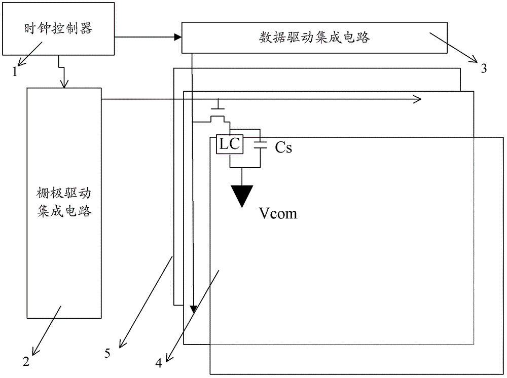
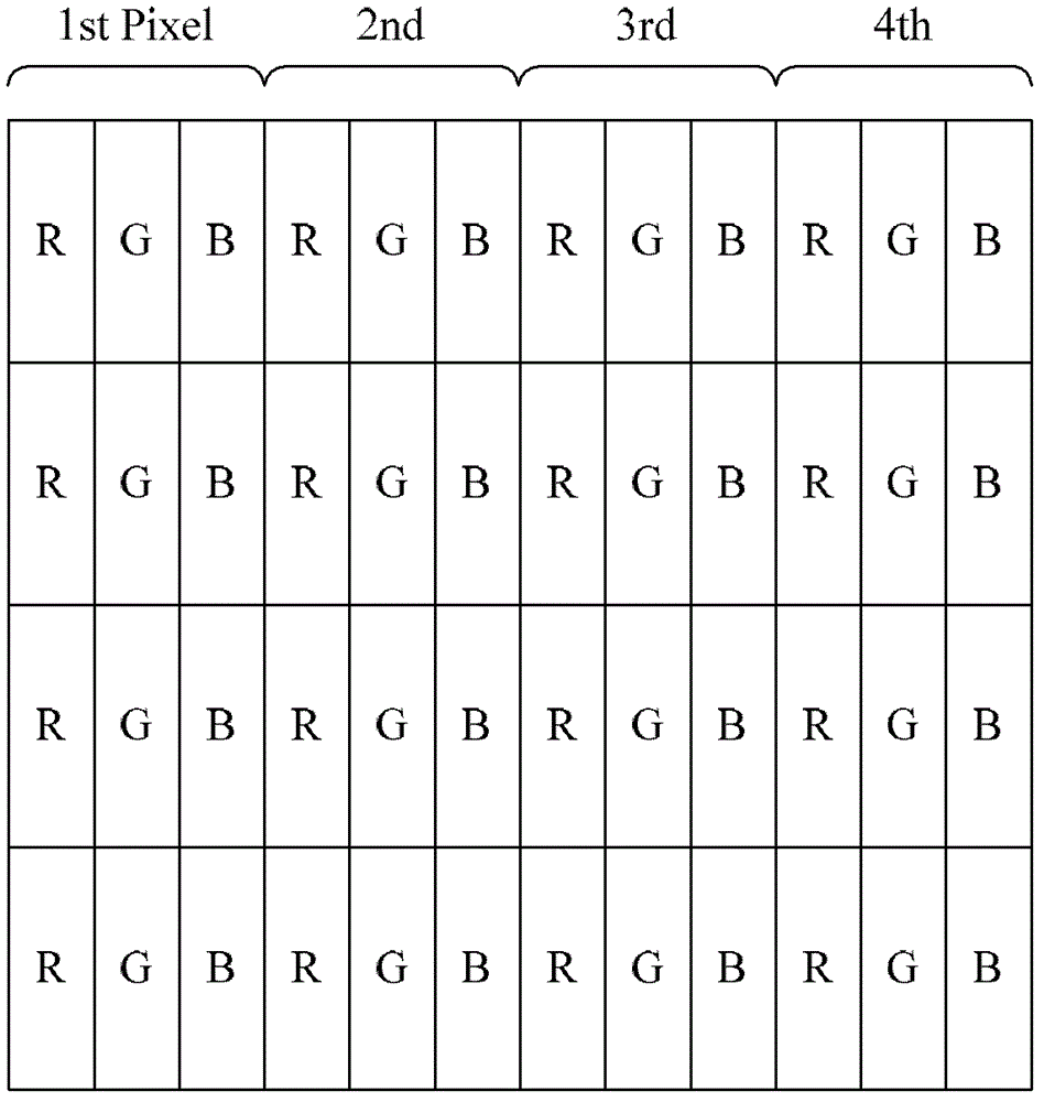
technical field [0001] The invention relates to the field of liquid crystal display, in particular to a liquid crystal display panel and its driving device and method. Background technique [0002] The structure of the current liquid crystal display panel is as follows: figure 1 shown. An LCD module consists of a display panel (Pixel Array) 4 with sub-pixels distributed, a data driver IC (Source Driver IC) 3 with data lines for driving the source of the sub-pixels, and a belt for driving the gates of the sub-pixels. It consists of a gate driver IC (Gate Driver IC) 2 and a backlight unit (Backlight Unit) 5, wherein the Source Driver IC 3 and Gate Driver IC 2 are connected to a clock controller (Timing Controller) 1. [0003] figure 2 A schematic diagram of an existing pixel array using three sub-pixels of red, green and blue (RGB) is shown, and each pixel is composed of three sub-pixels of RGB. At this stage, the application of RGB three-primary color technology cannot f...

Claims


Application Information

Patent Timeline
Patent Type & Authority Patents(China)
IPC IPC(8): G09G3/36G02F1/133
CPCG09G3/3607G09G3/3648G09G2300/0452G09G3/3614
Inventor 郭瑞
Owner BEIJING BOE OPTOELECTRONCIS TECH CO LTD
Why Eureka
Try Eureka