Backlight drive circuit

A technology of backlight driving circuit and driving voltage, applied in the field of backlight, can solve problems such as increased power consumption, and achieve the effect of reducing driving voltage and power consumption of backlight

Active Publication Date: 2018-11-20
BOE TECH GRP CO LTD +1
View PDF5 Cites 0 Cited by
  • Summary
  • Abstract
  • Description
  • Claims
  • Application Information

AI Technical Summary

Problems solved by technology

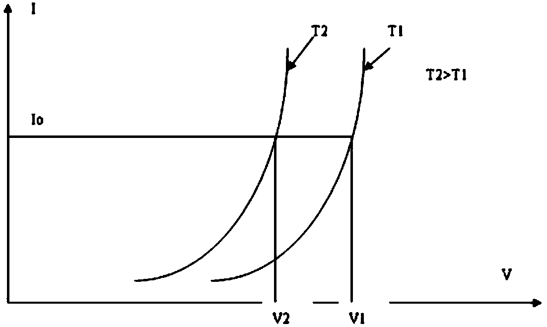
LED lights are physical components with PN junction characteristics. As the working time becomes longer, the current flowing through the LED will increase as the temperature rises under the same voltage, so the power consumption will also increase.

Method used


Image

  • Backlight drive circuit
  • Backlight drive circuit
  • Backlight drive circuit

Examples


Embodiment Construction

[0022] To make the objectives, technical solutions, and advantages of the embodiments of the present invention clearer, the embodiments of the present invention will be described in detail below with reference to the accompanying drawings. Obviously, the described embodiments are only a part of the embodiments of the present invention, rather than all the embodiments.

[0023] Throughout this specification, mentioning features, advantages or similar terms does not mean that all the features and advantages that can be achieved by the present invention should be in or in any single embodiment of the present invention. On the contrary, it should be understood that terms related to features and advantages mean that specific features, advantages, or characteristics described in conjunction with the embodiments are included in at least one embodiment of the present invention. Therefore, throughout this specification, discussions of features and advantages and similar language may refer...


PUM


Abstract

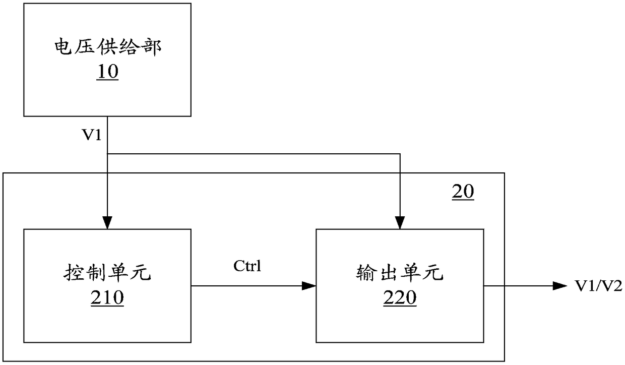
The present invention relates to a backlight driving circuit, which includes: a voltage supply part configured to supply a first driving voltage; outputting the first driving voltage to the light emitting element, and outputting a second driving voltage lower than the first driving voltage to the light emitting element when the ambient temperature of the light emitting element is higher than the preset threshold.

Description

Technical field [0001] The present invention relates to the field of backlight technology, and in particular to a backlight drive circuit. Background technique [0002] The backlight is an important part of the LCD module. The main working modules of the backlight source are LED (Light Emitting Diode (light emitting diode)) drivers and LED lamps. Therefore, the main aspects that affect the power consumption of the backlight source are the working voltage and working current of the LED lamp. [0003] The calculation formula for backlight power consumption is: power consumption = voltage × current. The LED lamp is a physical element with PN junction characteristics. As the working time becomes longer, the current flowing through the LED will increase as the temperature rises under the same voltage, so the power consumption also increases. Summary of the invention [0004] According to an aspect of the present invention, there is provided a backlight driving circuit, including: a vol...

Claims


Application Information

Patent Timeline
Patent Type & Authority Patents(China)
IPC IPC(8): G09G3/34H05B44/00
CPCG09G3/3406H05B45/18G09G2320/041H05B45/397Y02B20/30H05B45/46G02F1/133603G09G3/34
Inventor 孟昭晖
Owner BOE TECH GRP CO LTD
Why Eureka
Try Eureka