

Twinax cable
- Summary
- Abstract
- Description
- Claims
- Application Information
AI Technical Summary
Benefits of technology
Problems solved by technology
Method used
Image

Examples
Embodiment Construction
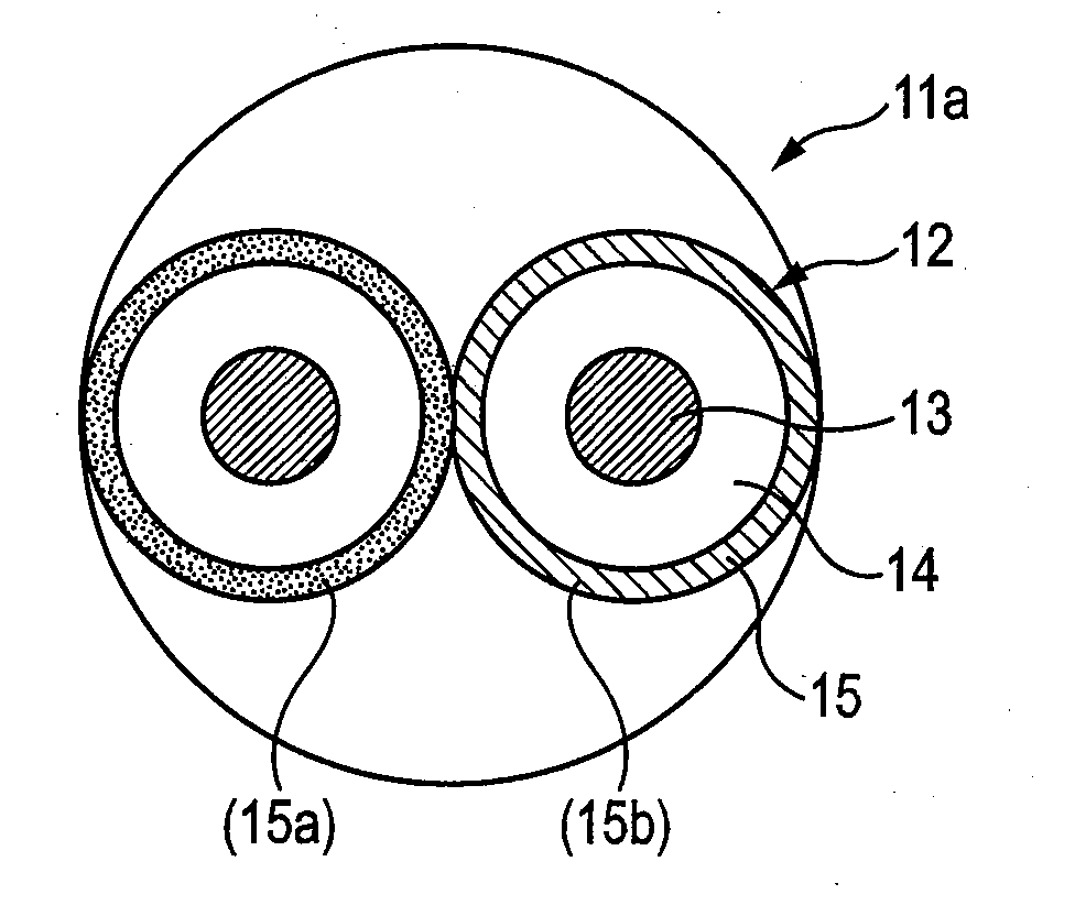
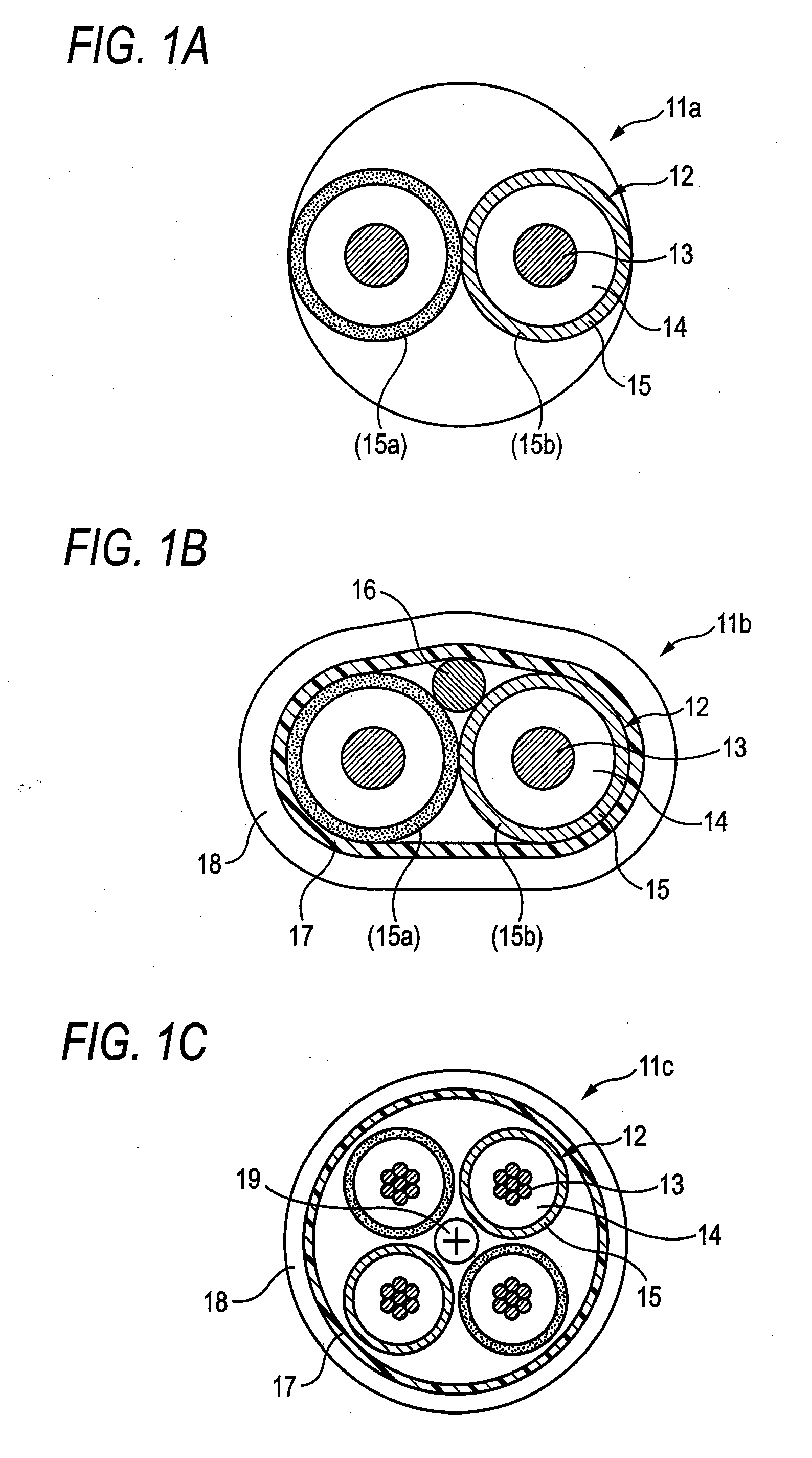
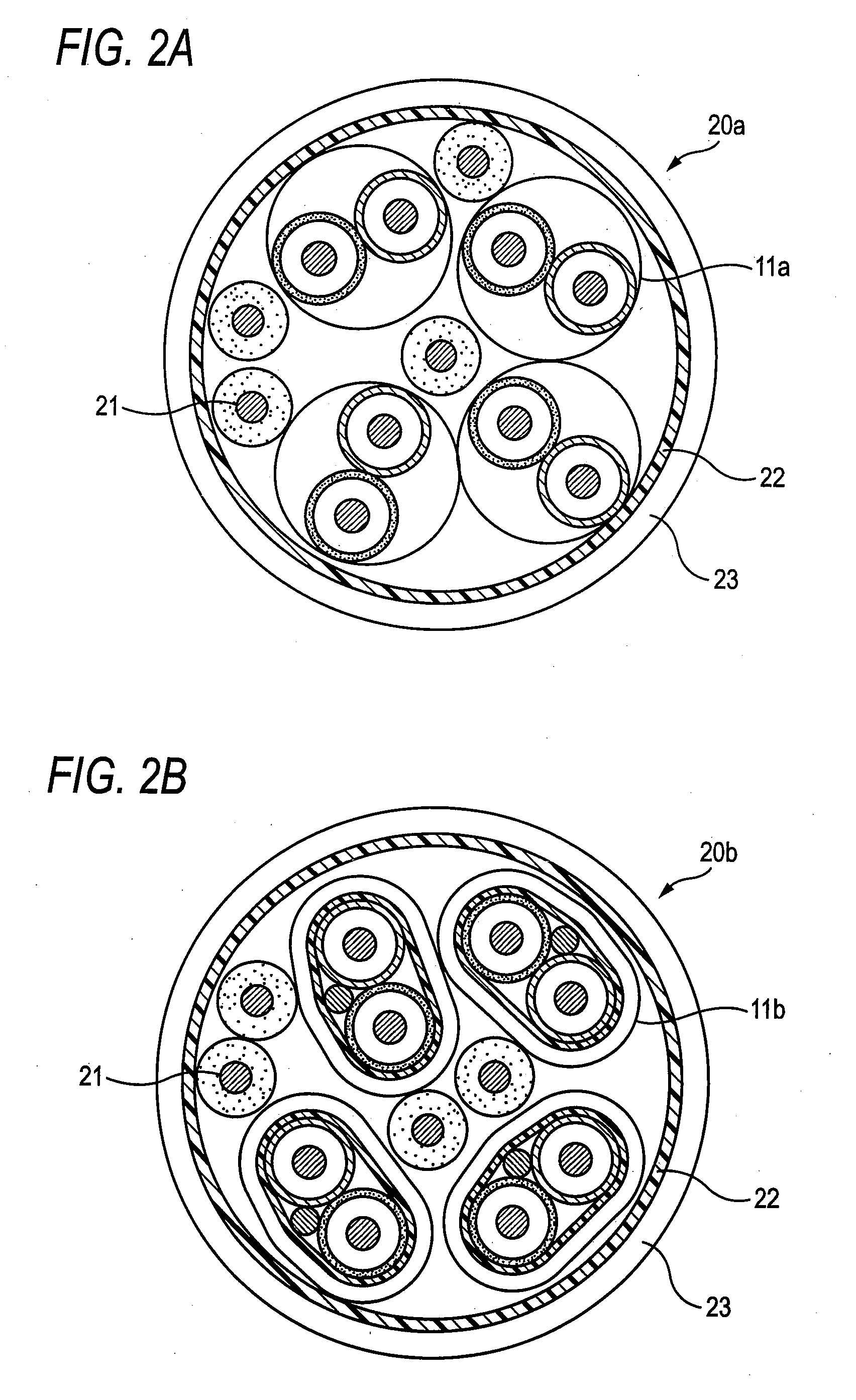
[0016]Exemplary embodiments of the present invention will be explained with reference to the drawings hereinafter. FIGS. 1A to 1C are views explaining twinax cables according to various embodiments of the present invention, and FIG. 2A and 2B are views showing examples of communication cables in which a plurality of twinax cables are assembled, respectively. In FIG. 1 and FIG. 2, 11a to 11b denote a twinax cable respectively, 11c denotes a quad cable,12 denotes a core wire, 13 denotes a conductor, 14 denotes an inner insulator, 15 denotes an outer insulator, 15a and 15b denote a hue respectively, 16 denotes a drain wire, 17 denotes a shield conductor, 18 denotes a jacket, 19 denotes a filler, 20a and 20b denote a communication cable respectively, 21 denotes an other wire, 22 denotes a common shield conductor, and 23 denotes a cable sheath.
[0017]The twinax cable according to the present invention can be applied to both a mode (twisted pair) in which two insulated wires whose conducto...
PUM
 Abstract
Description
Claims
Application Information