Light source unit and projector

a technology of light source unit and projector, which is applied in the direction of instruments, lighting and heating apparatus, optical elements, etc., can solve the problem of insufficient red light intensity

Active Publication Date: 2010-12-30
CASIO COMPUTER CO LTD
View PDF4 Cites 65 Cited by
  • Summary
  • Abstract
  • Description
  • Claims
  • Application Information

AI Technical Summary

Benefits of technology

[0008]According to a preferred aspect of the invention, there is provided a light source unit comprising a light emitting plate which has a plurality of segment areas on a base material and in which at least one of the plurality of segment areas is made into a reflecting portion, a luminescent material layer is formed on the reflecting area which emits light of a predetermined wavelength band by receiving excitation light, and at least one of the plurality of segment areas is made into a transmission portion which transmits light, a primary light source which shines excitation light on to a luminescent material on the luminescent material layer, a secondary light source which emits light of a wavelength band which is different from luminescent light emitted from the luminescent material layer and excitation light emitted from the primary light source, a collective optical system which collects light emitted from the light emitting plate and light emitted from the secondary light source so as to cause them to converge to the same optical path, and a light source control means which controls the emission of light from the primary light source and the secondary light source.

Problems solved by technology

However, since the luminous efficiency of the red luminescent material is lower than those of the other luminescent materials, there has been caused a problem that the luminance of red becomes insufficient.

Method used


Image

  • Light source unit and projector
  • Light source unit and projector
  • Light source unit and projector

Examples


Embodiment Construction

[0017]Hereinafter, a preferred mode for carrying out the invention will be described by use of the accompanying drawings. However, in the following embodiment, although various preferred technical limitations will be described as being made for carrying out the invention, the scope of the invention is not limited at all to the following embodiment and illustrated examples.

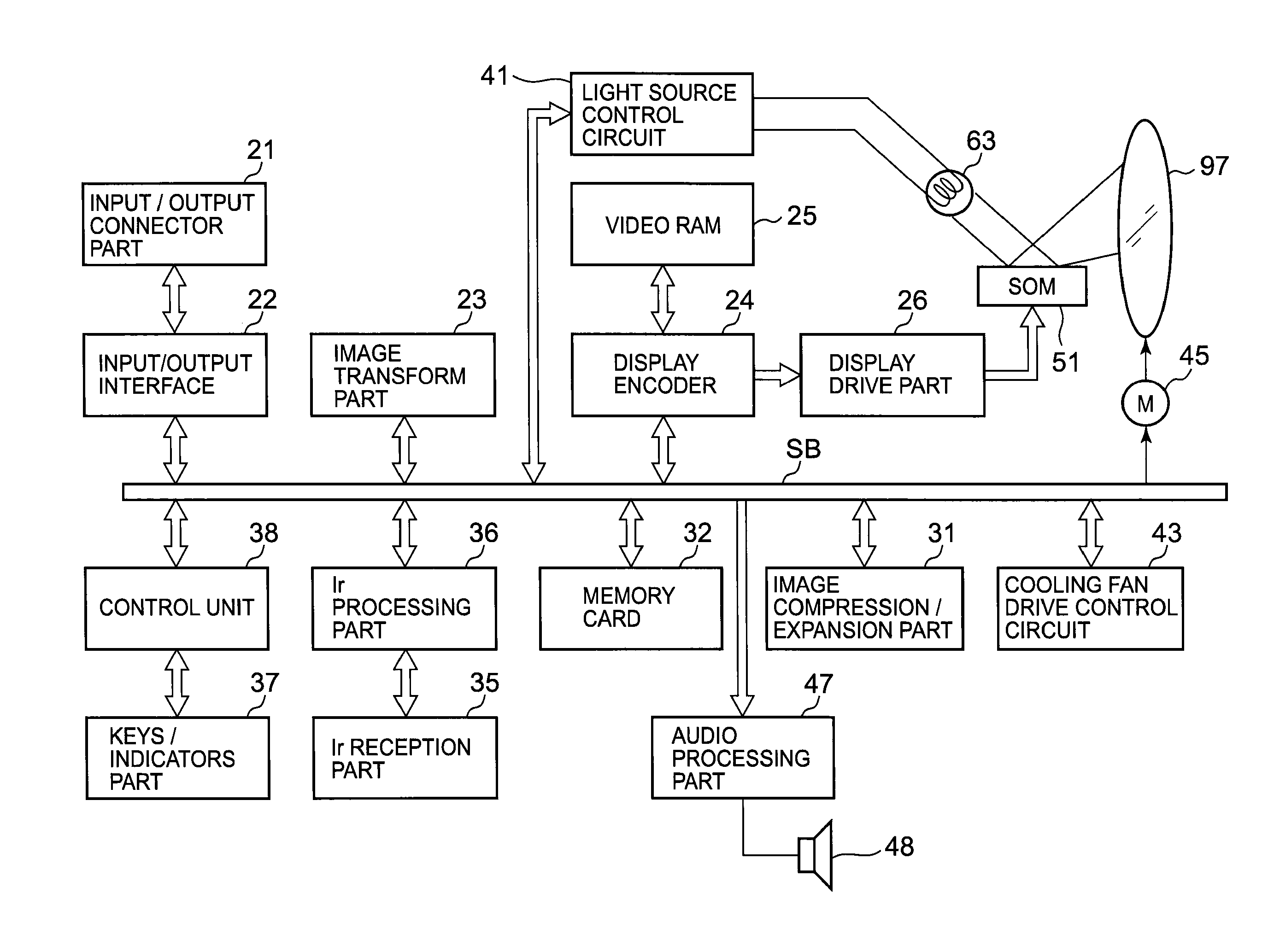
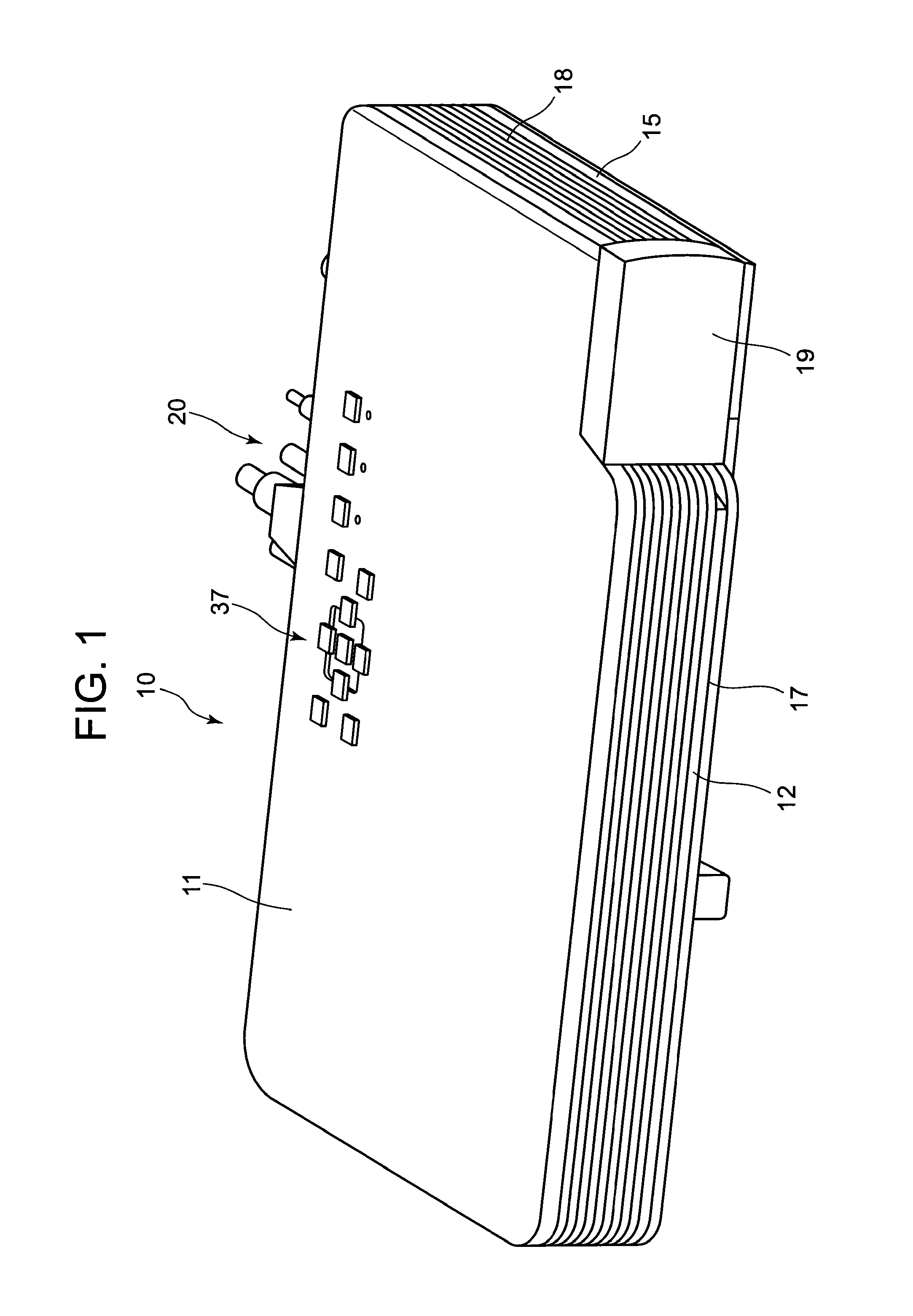
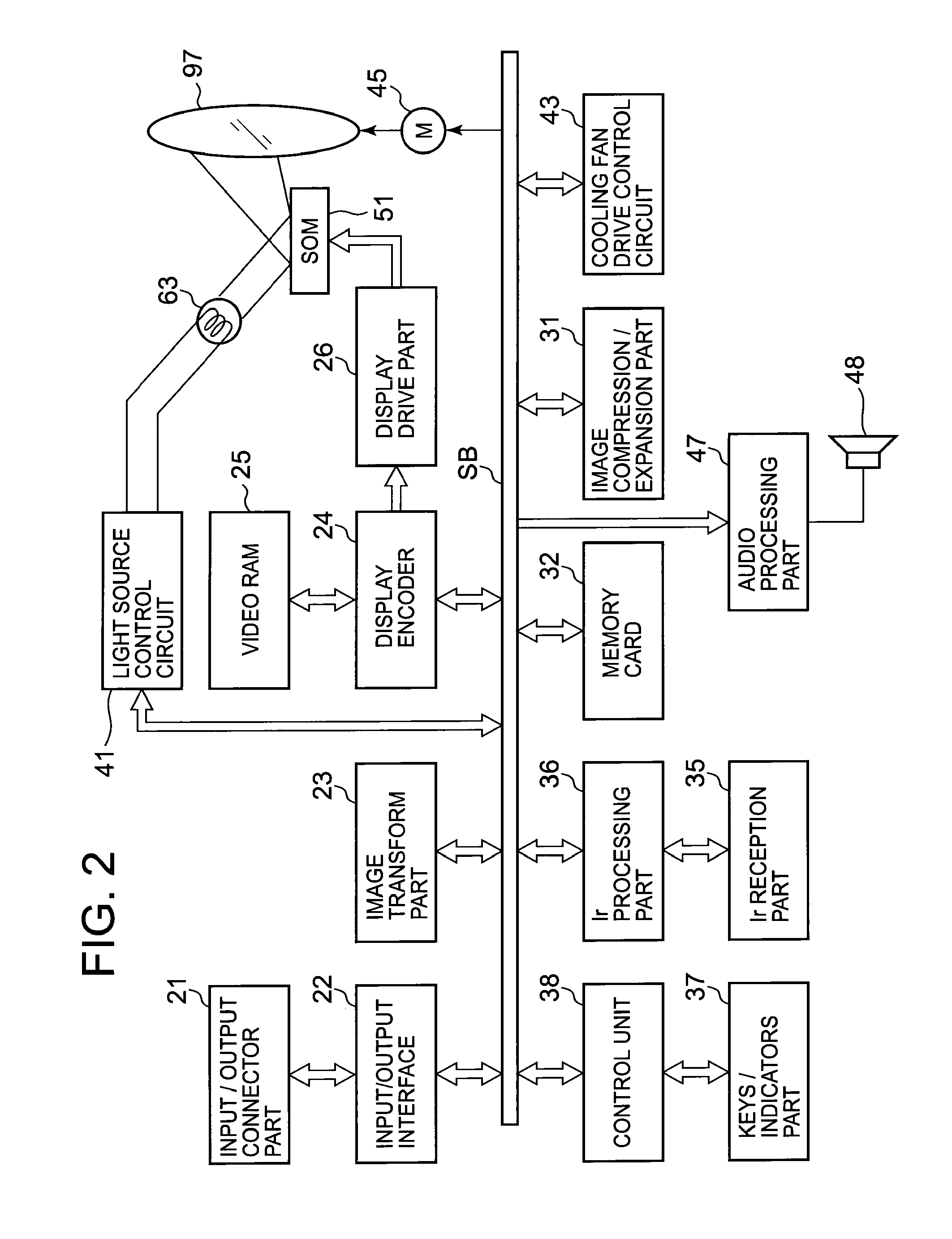
[0018]A projector 10 of the invention includes a light source unit 63, a display device 51, a cooling fan, a light source side optical system 62 for guiding light from the light source unit 63 to the display device 51, a projection side optical system 90 for projecting an image emitted from the display device 51 on to a screen, a projector control means for controlling the light source unit 63 and the display device 51, and a light source control circuit 41 which is a light source control means for controlling the emission of light from a primary light source 72 and a secondary light source 82 of the light source u...


PUM


Abstract

To provide a light source unit which can increase luminance and a projector including this light source unit. This light source unit includes a luminous wheel having a segment area on which a luminescent material layer is formed which emits light of a predetermined wavelength band by receiving light, and a segment area which is made into a transmission portion which transmits light, a primary light source which shines light of a visible wavelength band on to the luminous wheel, a secondary light source which emits light of a wavelength band which is different from light from the luminescent material layer and light from the primary light source, a collective optical system which collects light from the luminous wheel and the secondary light source to cause them to converge to the same optical path, and a light source control device which controls the emission of light from the light sources.

Description

CROSS-REFERENCE TO RELATED APPLICATIONS[0001]This application is based upon and claims the benefit of priority under 35 USC 119 of Japanese Patent Application No. 2009-155483 filed on Jun. 30, 2009, the entire disclosure of which, including the description, claims, drawings and abstract thereof, is incorporated herein by reference.BACKGROUND OF THE INVENTION[0002]1. Field of the Invention[0003]The present invention relates to a light source unit and a projector which includes the light source unit.[0004]2. Description of the Related Art[0005]In these days, data projectors are used on many occasions as image projection apparatuses which project images of screens and video images of personal computers, as well as images of image data stored in memory cards on to a screen. These projectors are such that light emitted from a light source is caused to converge to a micromirror device called DMD (Digital Micromirror Device) or a liquid crystal plate for display of a color image on the scr...

Claims


Application Information

Patent Timeline
Patent Type & Authority Applications(United States)
IPC IPC(8): G03B21/14H05B37/02
CPCG02B7/006G02B26/008G03B21/204G03B33/08G03B21/2013H04N9/3161H04N9/3164H04N9/3197F21V13/02H04N9/3117F21V13/08G03B21/20
Inventor MIYAZAKI, TAKESHI
Owner CASIO COMPUTER CO LTD
Why Eureka
Try Eureka