Linking mechanism for key switch assembly

Inactive Publication Date: 2011-02-17
ALL VISION GROUP
View PDF2 Cites 6 Cited by
  • Summary
  • Abstract
  • Description
  • Claims
  • Application Information

AI Technical Summary

Benefits of technology

[0007]The present invention has been accomplished under the circumstances in view. It is the main object of the present invention to provide a linking mechanism for key switch assembly, which is symmetrically configured to facilitate installation. It is another object of the present invention to provide a linking mechanism for key switch assembly, which prolongs the work life of the key switch assembly.
[0008]To achieve these and other objects of the present invention, a linking mechanism comprises a first link and a second link. The first link and the second link are obliquely coupled between a key cap and a positioning plate above a circuit module in a crossed manner for performing a scissor action to guide vertical movement of the key cap relative to the circuit module for enabling the key cap to be pressed by a user to trigger the circuit module in producing a control signal. Further, the first link and the second link are symmetrically configured in all directions. Therefore, it is not necessary to consider the installation direction of the first link and the second link when fastening the linking mechanism to the positioning plate and the key cap, facilitating fabrication and installation of the key switch assembly.
[0009]Further, the first link has two symmetrical narrow elongated base portions arranged in parallel and two symmet

Problems solved by technology

The asymmetrical configuration design limits installation of the linking mechanism to a particular direction

Method used


Image

  • Linking mechanism for key switch assembly
  • Linking mechanism for key switch assembly
  • Linking mechanism for key switch assembly

Examples


Example

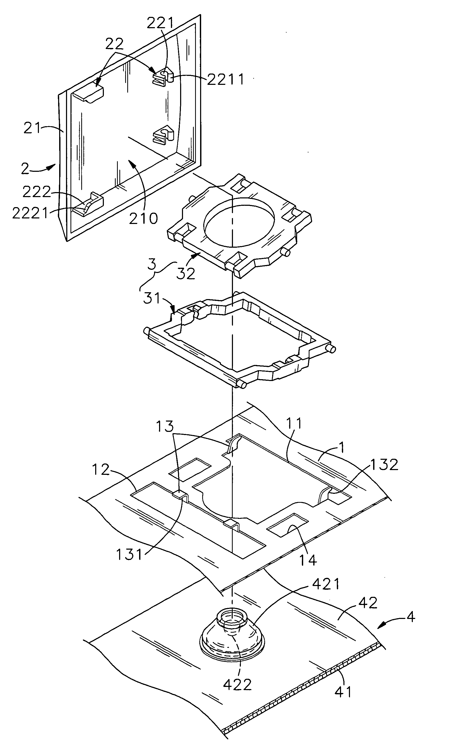
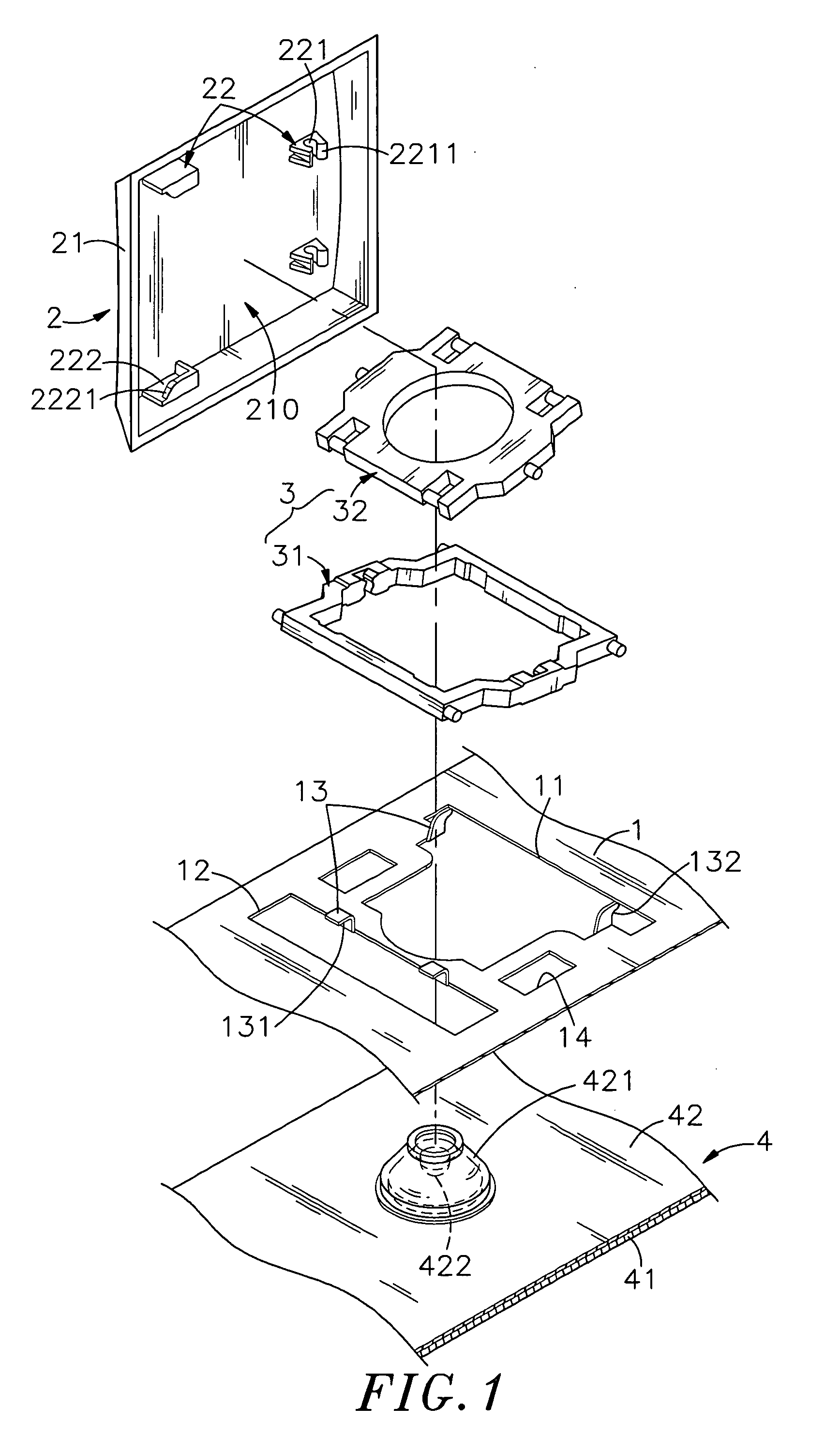
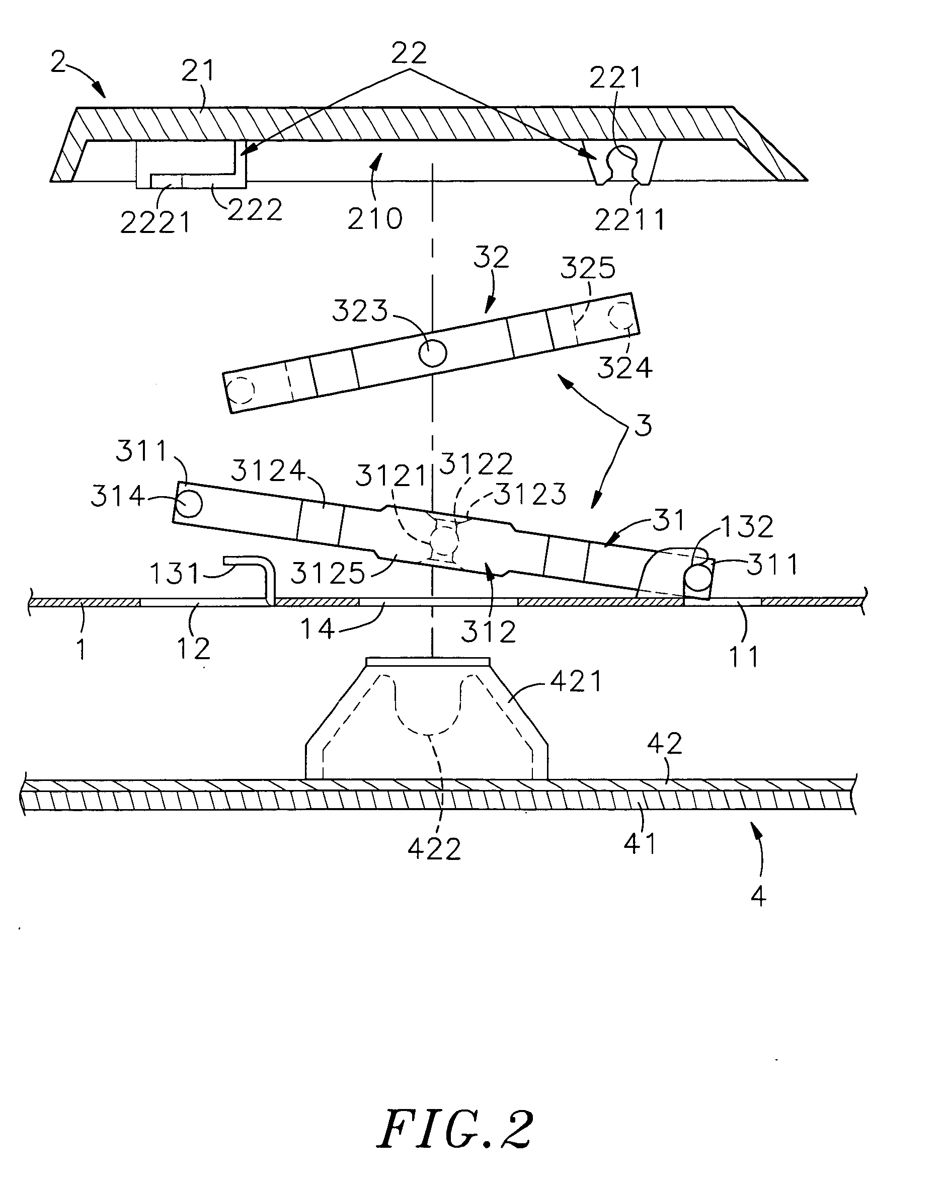
[0018]Referring to FIGS. 1˜4, a key switch assembly of an input device is shown comprising a positioning plate 1, a key cap 2, a linking mechanism 3 and a circuit module 4.

[0019]The positioning plate 1 has an opening 11 and a slot 12 cut through the top and bottom walls thereof and disposed adjacent to each other, and two pairs of coupling lugs 13 protruded from the top wall and respectively disposed at the border area of the opening 11 and the border area of the slot 12. The coupling lugs 13 are made having an angled or smoothly arched configuration. According to the present preferred embodiment, the two coupling lugs 13 that are disposed at one side of the slot 12 are angled lugs each defining a track 131; the two coupling lugs 13 that are disposed at the border area of the opening 11 at two opposite sides are smoothly arched lugs each defining a smoothly arched bottom retaining surface 132.

[0020]The key cap 2 is supported on the circuit module 4, having a hollow trapezoidal key c...


PUM


Abstract

A linking mechanism used in a key switch assembly is disclosed to include a first link, which is shaped like an open frame, and a second link, which is receivable within the first link. The first link and the second link are respectively symmetrically configured and obliquely coupled between a key cap and a positioning plate above a circuit module in a crossed manner for performing a scissor action to guide vertical movement of the key cap relative to the circuit module for enabling the key cap to be pressed by a user to trigger the circuit module in producing a control signal.

Description

BACKGROUND OF THE INVENTION[0001]1. Field of the Invention[0002]The present invention relates to an input device and more particularly, to a linking mechanism for use in a key switch assembly of an input device which has the first link and second link thereof symmetrically configured, facilitating installation.[0003]2. Description of the Related Art[0004]A conventional key switch structure for keyboard has a linking mechanism provided between a key cap and a bottom board to support vertical movement of the key cap. The linking mechanism may be made in the form of a cross-linkage (scissors-structure), rotary structure or sliding structure. FIG. 7 illustrates a scissor action design of key switch structure for input device according to the prior art. According to this design, the key switch structure comprises a bottom board C, a circuit board D supported on the bottom board C and carrying a rubber cone D1, a key cap B, and a linking mechanism A coupled between axle holders C1 of the ...

Claims


Application Information

Patent Timeline
IPC IPC(8): H01H13/705
CPCH01H2215/006H01H3/125
Inventor LIN, CHIH-CHERNG
Owner ALL VISION GROUP
Why Eureka
Try Eureka