Illuminated Brake Assembly and Wheel Well Accessory

Inactive Publication Date: 2014-11-20
HARRAGHY DAVID
View PDF22 Cites 5 Cited by
  • Summary
  • Abstract
  • Description
  • Claims
  • Application Information

AI Technical Summary

Benefits of technology

[0012]The present invention preferably encompasses the outer circumference or edge of a conventional automobile rotor. The present invention is preferably held in position via a series of external mounts designed to create a buffer between the rotor and the present invention, in order to prevent the present invention from overheating due to the heat absorbed by the rotor during the process of braking.
[0013]The present invention is preferably equipped with numerous LED bulbs placed along the exterior ridge of the ring of the present invention. The LED bulbs are configured to project light

Problems solved by technology

While this is still practiced in some districts, many areas of the world have enacted legislation in order to ban this type of exterior vehicle lighting, citing that it can be distracting to other drivers.
Many forms of exterior lights have been created to illuminate the wheel well of a conventional vehicle

Method used


Image

  • Illuminated Brake Assembly and Wheel Well Accessory
  • Illuminated Brake Assembly and Wheel Well Accessory
  • Illuminated Brake Assembly and Wheel Well Accessory

Examples


Example

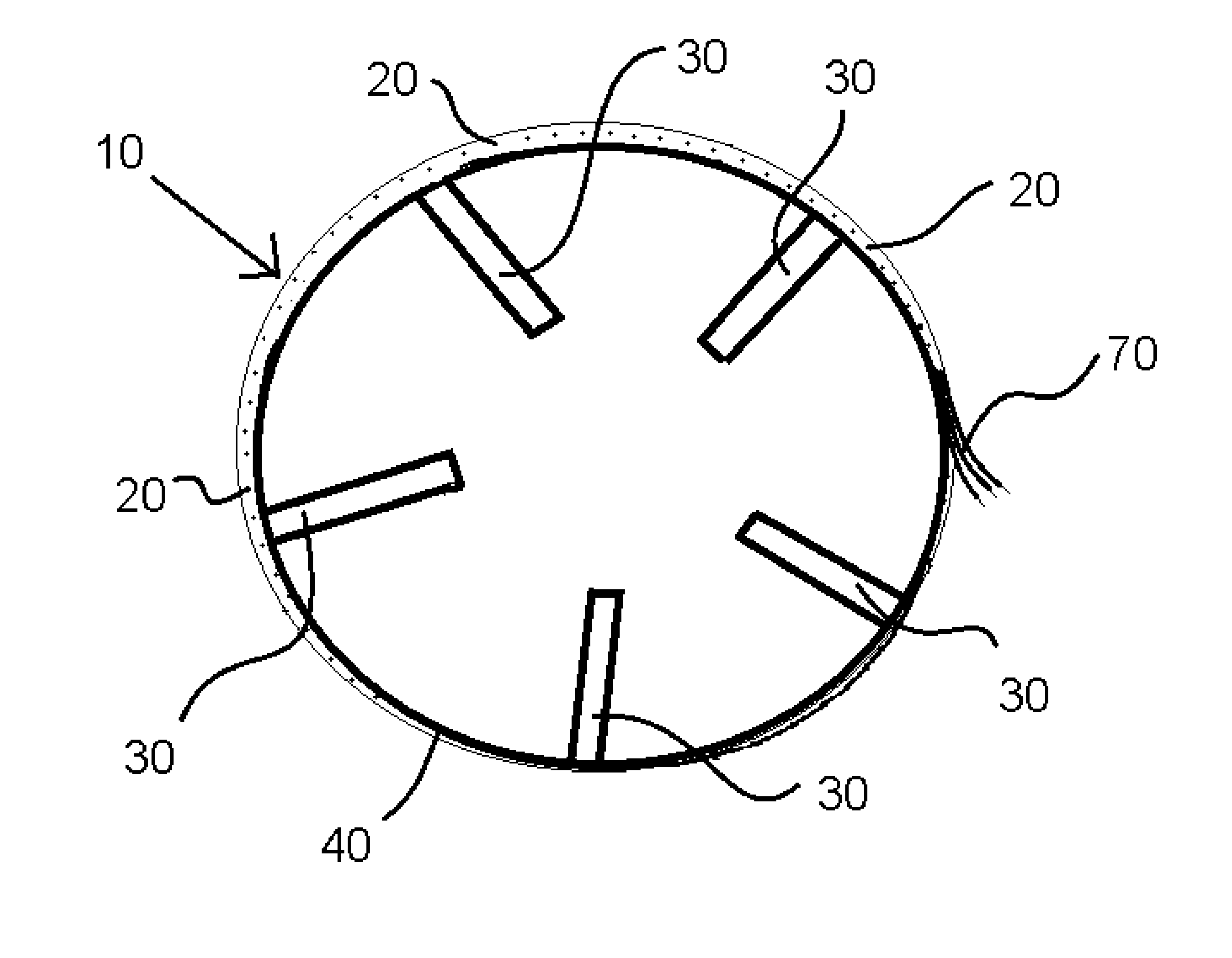
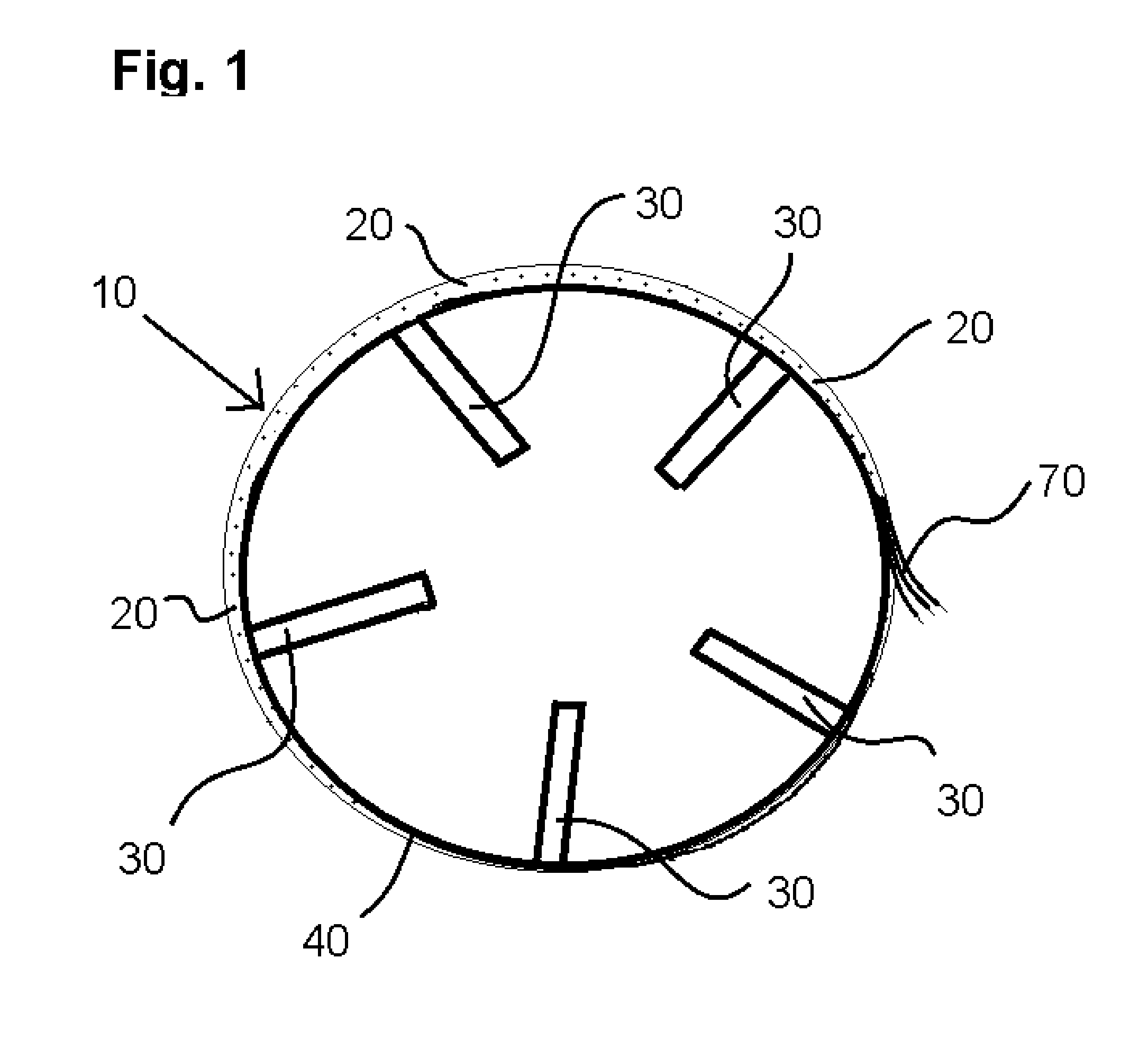
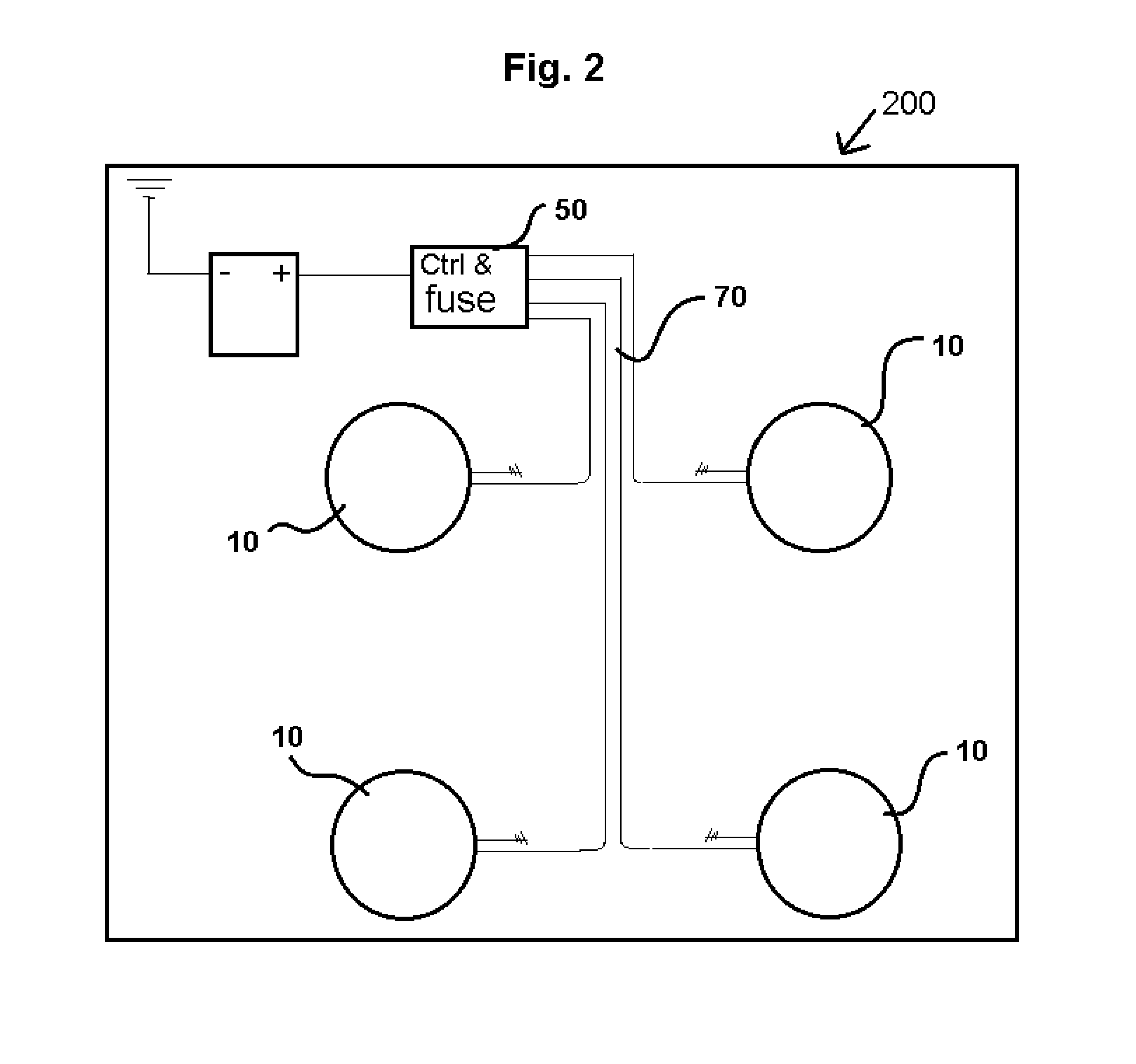
[0021]The present invention is an illumination system for the wheel-well area of a vehicle. More specifically, the present invention is designed to illuminate within the space found between the brake and rotor assembly of a vehicle and the rim and wheel assembly of the vehicle. Illumination is preferably provided via a ring (10) equipped with a series of LED lights (20), preferably placed equidistant from each other along the circumference of the ring. The LED lights (20) of the ring are preferably powered via direct current (DC) power supplied from the conventional 12 volt battery found in most contemporary vehicles. The ring (10) is preferably designed to be custom-sized according to the specific dimensions of the rotors of the vehicle it is to be installed on.

[0022]The ring (10) of the present invention is preferably composed of a soft or semi-malleable metal, in order to facilitate the casting of the ring (10), the installation of the ring (10) on to the vehicle, as well as the ...


PUM


Abstract

An accessory for the wheel-well of a vehicle that is equipped with a series of lights designed to illuminate the inner portion of the space that exists between the brake rotors and the rim of the wheel in a conventional automobile. A series of LED lights are configured to project light from a ring that lines the brake rotor and brake caliper of a vehicle's brake assembly. Light is preferably projected in a 180 degree radius from the ring, which illuminates the rim of the wheel assembly, a portion of the ground beneath the vehicle, and portions of the wheel-well.

Description

CONTINUITY[0001]This application is a non-provisional application of provisional application No. 61 / 824,432, filed on May 17, 2013, and priority is claimed thereto.FIELD OF THE PRESENT INVENTION[0002]The present invention relates to exterior automobile modification. More specifically, the present invention relates to exterior automotive lights, specifically those positioned on or around the wheel assembly or wheel-well of a vehicle. The present invention is designed to be placed in a position outside the circumference of the rotor and brake caliper assembly. The present invention preferably rounds around the exterior of the rotor and brake caliper of the disc brake assembly of a conventional wheel assembly.BACKGROUND OF THE PRESENT INVENTION[0003]Owners of automobiles have often sought to customize their vehicles in order to make them unique or stand out in a crowd. Modifications in the form of after-market parts have been created for nearly every facet of an automobile's interior a...

Claims


Application Information

Patent Timeline
IPC IPC(8): B60Q1/32
CPCB60Q1/326B60Q2900/10B60Q2900/30
Inventor HARRAGHY, DAVID
Owner HARRAGHY DAVID
Why Eureka
Try Eureka