
Lighted Floor Panels and Portable Lighted Stage Systems Comprised of Same

Inactive Publication Date: 2013-12-05
CANTU JOSE +1
View PDF14 Cites 7 Cited by
  • Summary
  • Abstract
  • Description
  • Claims
  • Application Information

AI Technical Summary

Benefits of technology

This patent describes a lighted floor system that is durable and can be easily installed and removed. It is made up of interlocking modules that can withstand heavy use and is supported by thin light panels. The light panels are designed to be easily replaced if damaged, with a protective sheet that can be easily removed and replaced. Overall, this design allows for a highly durable and flexible lighted floor system that can be used repeatedly in different locations.

Problems solved by technology

Lighted floor systems are hardly new.
Many interesting arrangements of lighted floors taught throughout the years provide excellent results and performance yet they do not support portability.
As such, Harrison's modular floors are not good candidates for applications where reinstallation is desirable.
While these floor mats are indeed ‘portable’ and ‘removable’, they are nevertheless comprised of many structures and features which render them less than ideal for use in larger area staging applications.
This construction is not suitable for use as temporary staging systems.
The device is well-suited for color illuminated floors of high brightness and saturation however, the systems presented by Philips do not support portability and reinstallation.
While they provide high brightness performance in a thin package, the systems do not include provisions for improved uniformity of the illumination field.
In addition as the wear surface is permanently affixed to the waveguide, lifetime is limited to the life of that surface which remains susceptible to heavy wear and is easily damaged through thus rendering the entire system suitable for very light duty applications only.

Method used


Image

  • Lighted Floor Panels and Portable Lighted Stage Systems Comprised of Same
  • Lighted Floor Panels and Portable Lighted Stage Systems Comprised of Same
  • Lighted Floor Panels and Portable Lighted Stage Systems Comprised of Same

Examples


Embodiment Construction

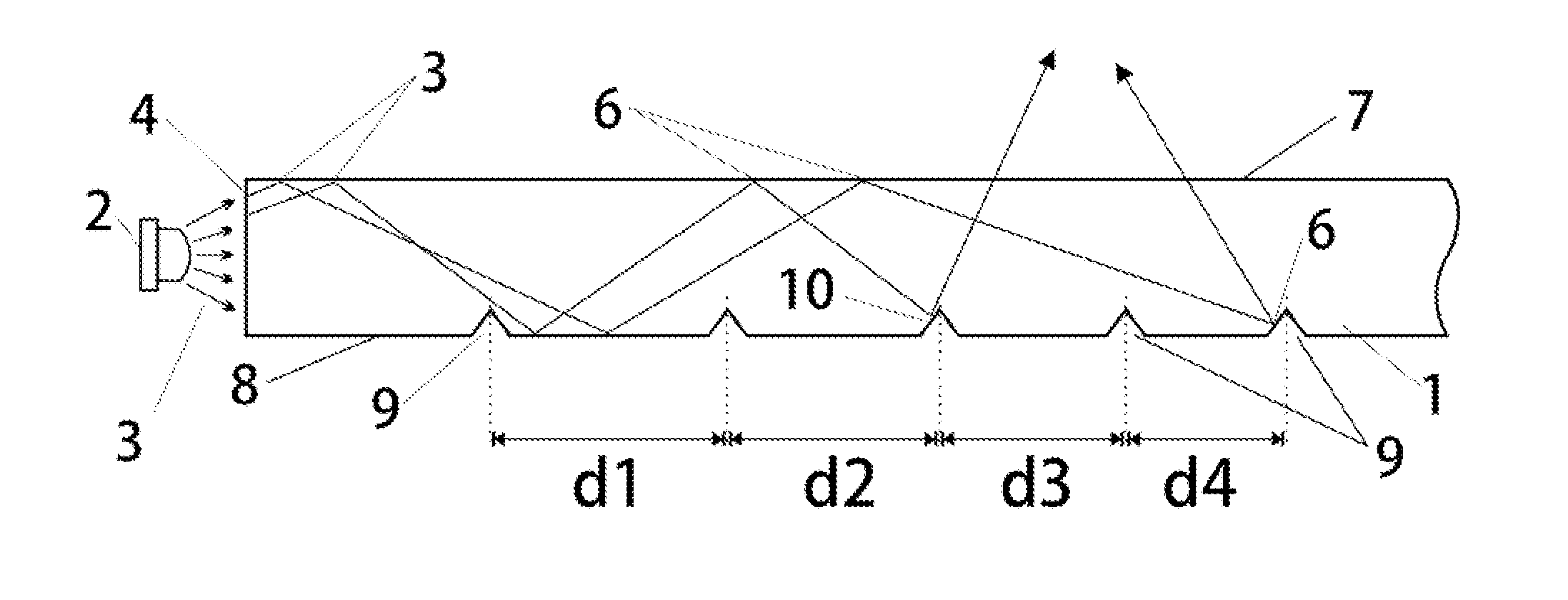
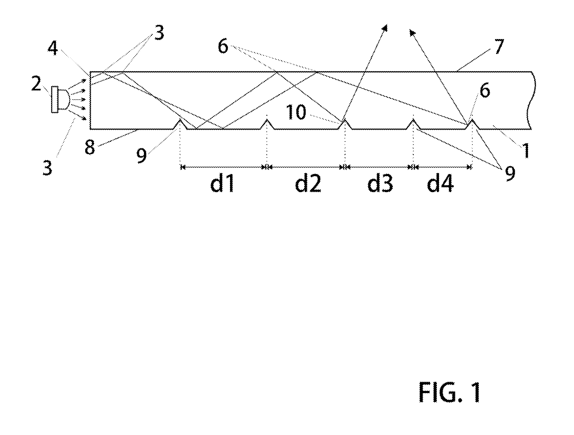
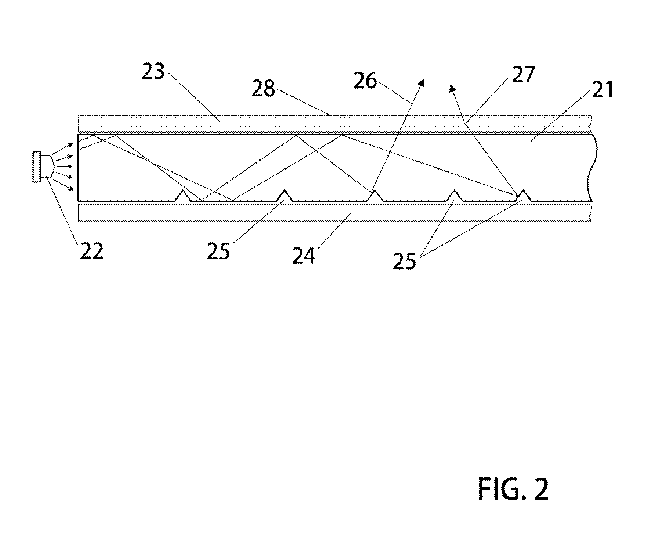
[0034]The foundation upon which most preferred versions of these systems are built includes a side illuminated waveguide 1. These waveguides are characterized as large two-dimensional planar slabs of optically transparent material of high strength and durability. One important useful material which is suitable in most versions is a Plexiglas plastic material. A light source 2 such as a high brightness LED or laser semiconductor emits light when stimulated by electrical current. Light rays 3 emitted by light sources may enter the waveguide at an optically polished face 4. Light rays propagate within the waveguide and are substantially contained therein in part by total internal reflections 6 at the waveguide top 7 and bottom 8 surfaces. The bottom surface may be specially prepared with ‘scoring’ or surface ‘imperfections’ or disruptions to the otherwise optically smooth surface. Scored grooves 9 for example provide sites which tend to interrupt regular internal reflections and thus w...


PUM


Abstract

A lighted floor system has been invented to facilitate quick temporary installation, and ease of removal whereby the floor is particularly suitable for highly durable applications. A durable and inexpensive modular system permits these devices to be used as flooring for high-performance lighted stage is suitable for use in concerts and other performing art expositions. In particular, these lighted floor systems presented herein are formed of a ‘repeat unit’ element which may be affixed to similar or identical units in a paving scheme to cover a large area floor space. Each repeat unit includes one or more light panels to provide highly dynamic color light outputs of high uniformity with respect to the illumination fields. These panels include a construction suitable for high durability—i.e. they support being walked on; highly portable they support quick installation—uninstallation; and are quite inexpensive due to their unique construction.

Description

BACKGROUND OF THE INVENTION[0001]1. Field[0002]The following invention disclosure is generally concerned with portable stage equipment and specifically concerned with highly durable lighted flooring systems suitable for use as concert staging.[0003]2. Background[0004]Lighted floor systems are hardly new. Indeed the art is replete with clever arrangements, each of which provide useful characteristics and attributes particular to those designs in view of the objectives for which they serve. In most versions up to recent times, incandescent bulbs were used as light sources. Because light emitting diodes now produce light in very high intensity, there are significant advantages to arrange lighted floor systems about LEDs. Some of the more modern lighted floor systems found in the art include LED based systems and designs based upon LED light sources are fundamentally different that those of previously used sources.[0005]In some particular illustrative examples, early designers and inven...

Claims


Application Information

Patent Timeline
IPC IPC(8): F21S8/00F21V8/00
CPCF21V33/006F21V2200/20
Inventor CANTU, JOSEGOMEZ, ALFREDO
Owner CANTU JOSE
Learn More