Conductive member, and charging roller, process cartridge and image forming apparatus using same

Active Publication Date: 2007-03-22
RICOH KK
View PDF6 Cites 5 Cited by
  • Summary
  • Abstract
  • Description
  • Claims
  • Application Information

AI Technical Summary

Benefits of technology

[0015] The present invention was devised in view of the aforementioned problems of the prior art, an object thereof being to provide a highly durable conductive member which can maintain a stabl

Problems solved by technology

However, a contact charging method involves problems of the following kind.
In particular, the seeping described above makes toner adherence more liable to occur.
Furthermore, the charging roller which makes contact with the charged body oscillates when an AC voltage is applied to the charging roller, and this creates a charging sound.
Moreover, the toner on the photosensitive body becomes attached to the charging roller, and this causes charging performance to decline.
Yet further, if the photosensitive body is halted for a long period of time, the material constituting the charging roller becomes attached to the photosensitive body and the charging roller suffers permanent deformation.
However, although the proximity charging method has is the advantages described above in comparison with a contact charging method, it involves the following two problems, which make practical application difficult.
More specifically, in the proximity charging method, it is difficult to maintain a uniform gap between the charging member and the photosensitive body, and furthermore, charging non-uniformities are liable to occur due to variation in the gap between the charging member and the photosensitive body.
When charging non-uniformities occur, they can give rise to image defects, such as adherence of toner to white areas of the paper.
As a device for maintaining the gap between the charging roller and the photosensitive body, Japanese Patent Application Publication No. 2001-296723, for example, discloses a non-contact charging apparatus in which a jointed tape-shaped member is installed as a gap management member on the outer circumference of either end section of an elastic roller section, thereby forming a gap with respect to the surface of an image carrier, and although it resolves the problems described above in the short term, the elastic rubber used for the charging roller is liable to suffer flatting over time, and w

Method used


Image

  • Conductive member, and charging roller, process cartridge and image forming apparatus using same
  • Conductive member, and charging roller, process cartridge and image forming apparatus using same
  • Conductive member, and charging roller, process cartridge and image forming apparatus using same

Examples


Example

EXAMPLE 1

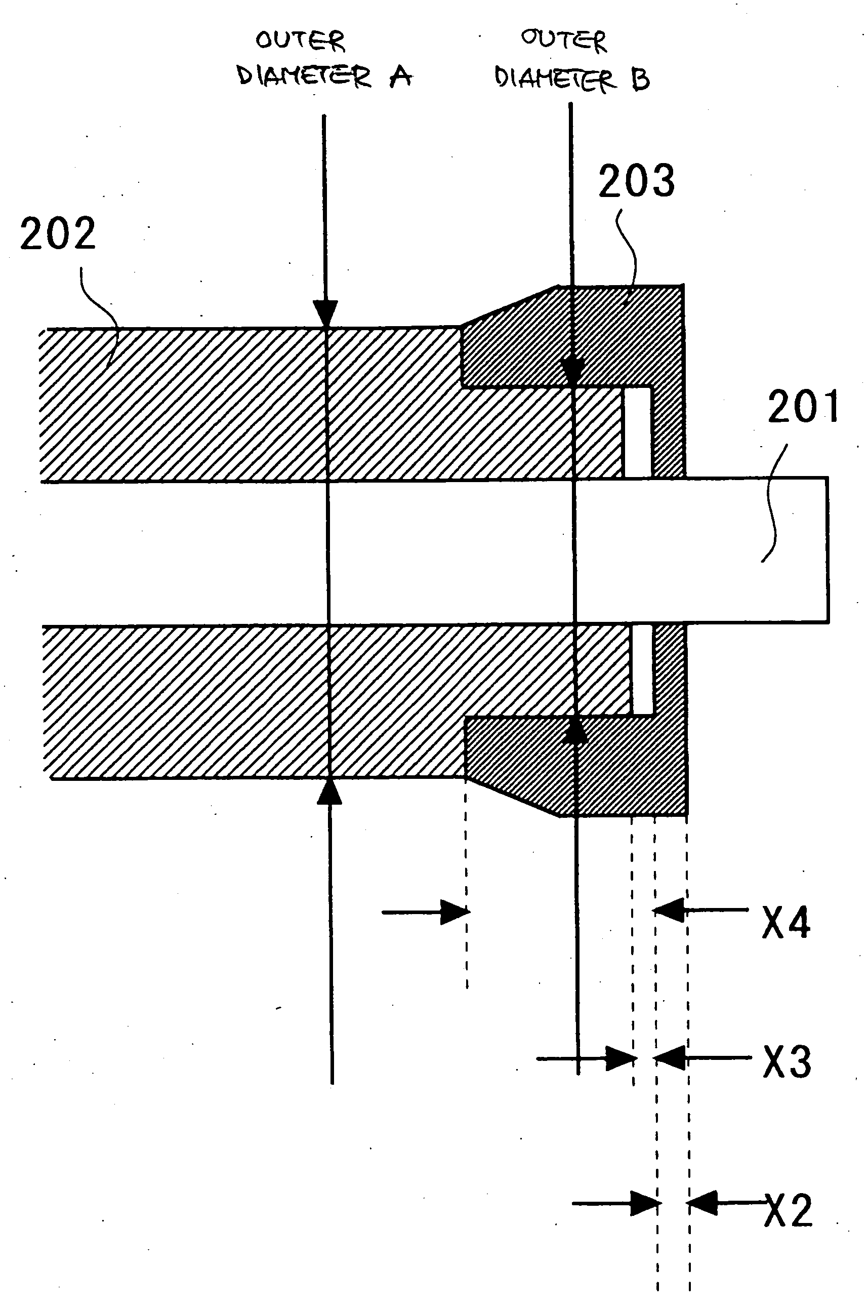
[0080] A resin composition (intrinsic volume resistance: 2×10⁸ Ωcm) comprising 50 wt % of ABS resin (Denka ABS GR-0500, made by Denki Kagaku Kogyo Co.) and 50 wt % of polyester ester amide (IRGASTAT P18, made by Chiba Specialty Chemicals) was coated by ejection molding to create an electrical resistance adjusting layer 202 on a core axis of stainless steel (outer diameter 8 mm), thereby forming an electrical resistance adjusting layer 202 having an external diameter of 14 mm, and an external diameter in the reduced diameter sections at either end of 11.3 mm. Subsequently, ring-shaped gap maintaining members made of high-density polyethylene resin (Novatech PP HY540, made by Polygem Japan) were fitted and bonded onto the reduced diameter sections on either end of the electrical resistance adjusting layer 202, in order to form gap maintaining members 203.

[0081] Thereupon, cutting was carried out to simultaneously finish the outer diameter (maximum diameter) of the gap maint...

Example

EXAMPLE 2

[0082] A resin composition (intrinsic volume resistance: 2×10⁸ Ωcm) comprising 50 wt % of ABS resin (Denka ABS GR-0500, made by Denki Kagaku Kogyo Co.) and 50 wt % of polyester ester amide (IRGASTAT P18, made by Chiba Specialty Chemicals) was coated by ejection molding to create an electrical resistance adjusting layer 202 on a core axis of stainless steel (outer diameter 8 mm), thereby forming an electrical resistance adjusting layer 202 having an external diameter of 14 mm, and an external diameter in the reduced diameter sections at either end of 11.1 mm. Subsequently, ring-shaped gap maintaining members made of high-density polyethylene resin (Novatech PP HY540, made by Polygem Japan) were fitted and bonded onto the reduced diameter sections on either end of the electrical resistance adjusting layer 202, in order to form gap maintaining members 203.

[0083] Thereupon, cutting was carried out to simultaneously finish the outer diameter (maximum diameter) of the gap maint...

Example

EXAMPLE 3

[0084] A resin composition (intrinsic volume resistance: 2×10⁸ Ωcm) comprising 50 wt % of ABS resin (Denka ABS GR-0500, made by Denki Kagaku Kogyo Co.) and 50 wt % of polyester ester amide (IRGASTAT P18, made by Chiba Specialty Chemicals) was coated by ejection molding to create an electrical resistance adjusting layer on a core axis of stainless steel (outer diameter 8 mm), thereby forming an electrical resistance adjusting layer 202 having an external diameter of 14 mm, and an external diameter in the reduced diameter sections at either end of 10.9 mm. Subsequently, ring-shaped gap maintaining members 203 made of high-density polyethylene resin (Novatech PP HY540, made by Polygem Japan) were fitted and bonded onto the reduced diameter sections on either end of the electrical resistance adjusting layer, in order to form gap maintaining members.

[0085] Thereupon, cutting was carried out to simultaneously finish the outer diameter (maximum diameter) of the gap maintaining m...


PUM


Abstract

A conductive member forming a charging roller having high durability which maintains a stable gap with respect to an abutting member, comprising a long conductive supporting body, an electrical resistance adjusting layer, and gap maintaining members, wherein, taking X2 to be the thickness of the portions of the gap maintaining members which oppose the end faces of the electrical resistance adjusting layer, the relationship 1 mm≦X2≦3 mm is satisfied, taking X3 to be the interval between the end faces of the electrical resistance adjusting layer and the gap maintaining members which oppose these end faces, the relationship 0.1≦X3≦1 mm is satisfied, and taking X4 to be the interval from the faces of the gap maintaining members opposing the end faces of the electrical resistance adjusting layer, to the step difference faces of the reduced diameter sections of the electrical resistance adjusting layer, then X4 is 5 mm or greater, and is shorter than the length from the faces of the gap maintaining members which oppose the end faces of the electrical resistance adjusting layer to the positions on the electrical resistance adjusting layer opposing the end sections which correspond to the image forming region of the photosensitive body.

Description

BACKGROUND OF THE INVENTION [0001] 1. Field of the Invention [0002] The present invention relates to a conductive member which is disposed in the vicinity of the image carrier of an image forming apparatus of an electrophotographic type and is used as a charging member, transfer member, or the like, and in particular, it relates to a charging roller, process cartridge and image forming apparatus which use such a conductive member. [0003] 2. Description of the Background Art [0004] Conventionally, in an image forming apparatus of an electrophotographic type, such as a copying machine, a laser beam printer, or a facsimile machine, conductive members are used as a charging roller which applies charge to an image carrier (also called “photosensitive body” below), and as a transfer. roller which performs transfer processing of toner on the photosensitive body. [0005] For example, as prior art technology relating to an image forming apparatus using a charging roller of this kind, Japanese...

Claims


Application Information

Patent Timeline
IPC IPC(8): G03G15/02
CPCG03G15/0208G03G15/025G03G2215/025
Inventor SHIMOJO, EIJIKAWASUMI, MASANORIKIMURA, YOSHIYUKISATOH, MASAHIKOUCHITANI, TAKESHIZEMBA, HIDEKINARITA, YUTAKAHASHIMOTO, SHUNICHIMURAKAMI, EISAKUKAYAHARA, SHIN
Owner RICOH KK
Why Eureka
Try Eureka