

Micro-cavity MEMS device and method of fabricating same
- Summary
- Abstract
- Description
- Claims
- Application Information
AI Technical Summary
Benefits of technology
Problems solved by technology
Method used
Image

Examples
Embodiment Construction
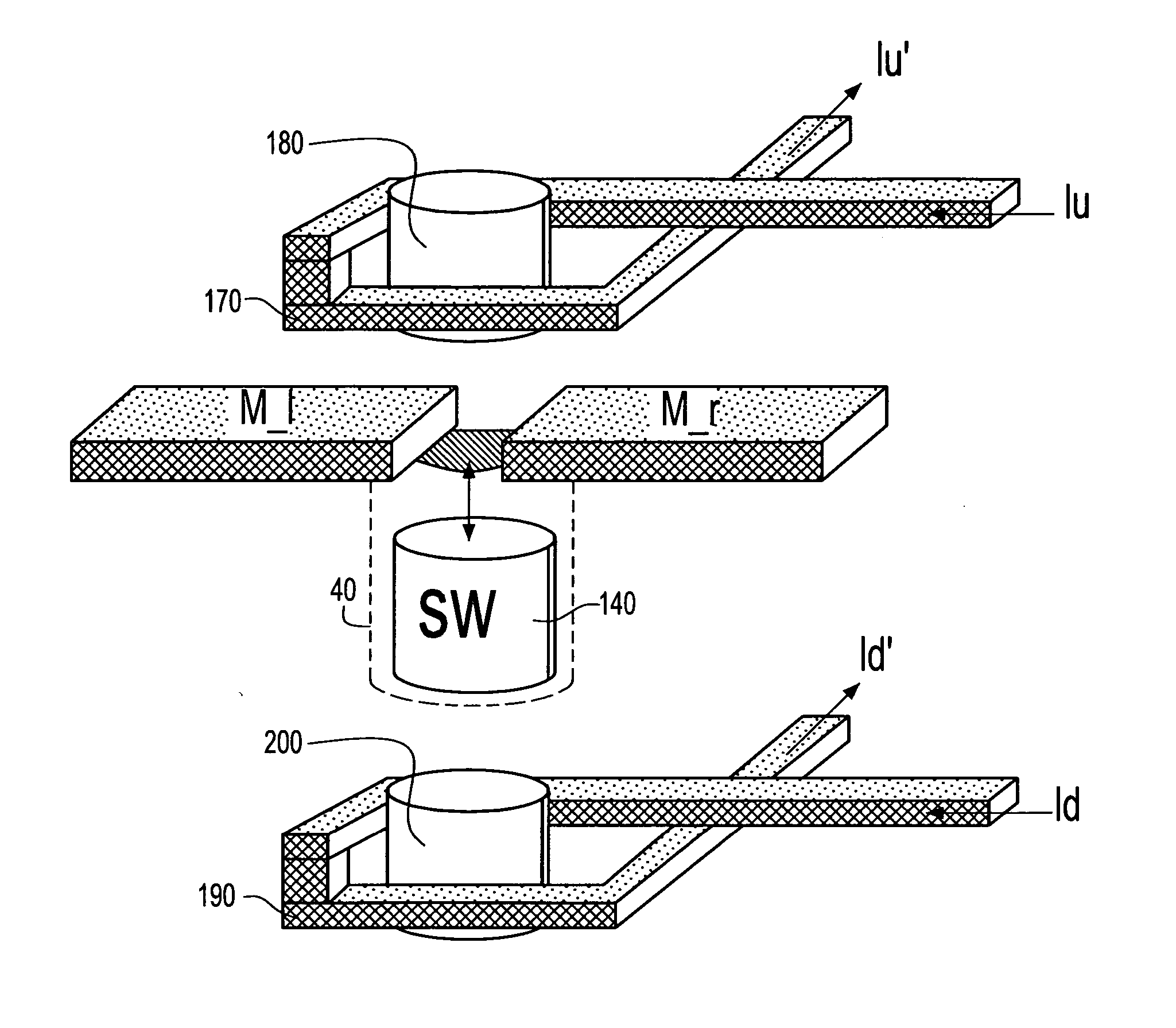
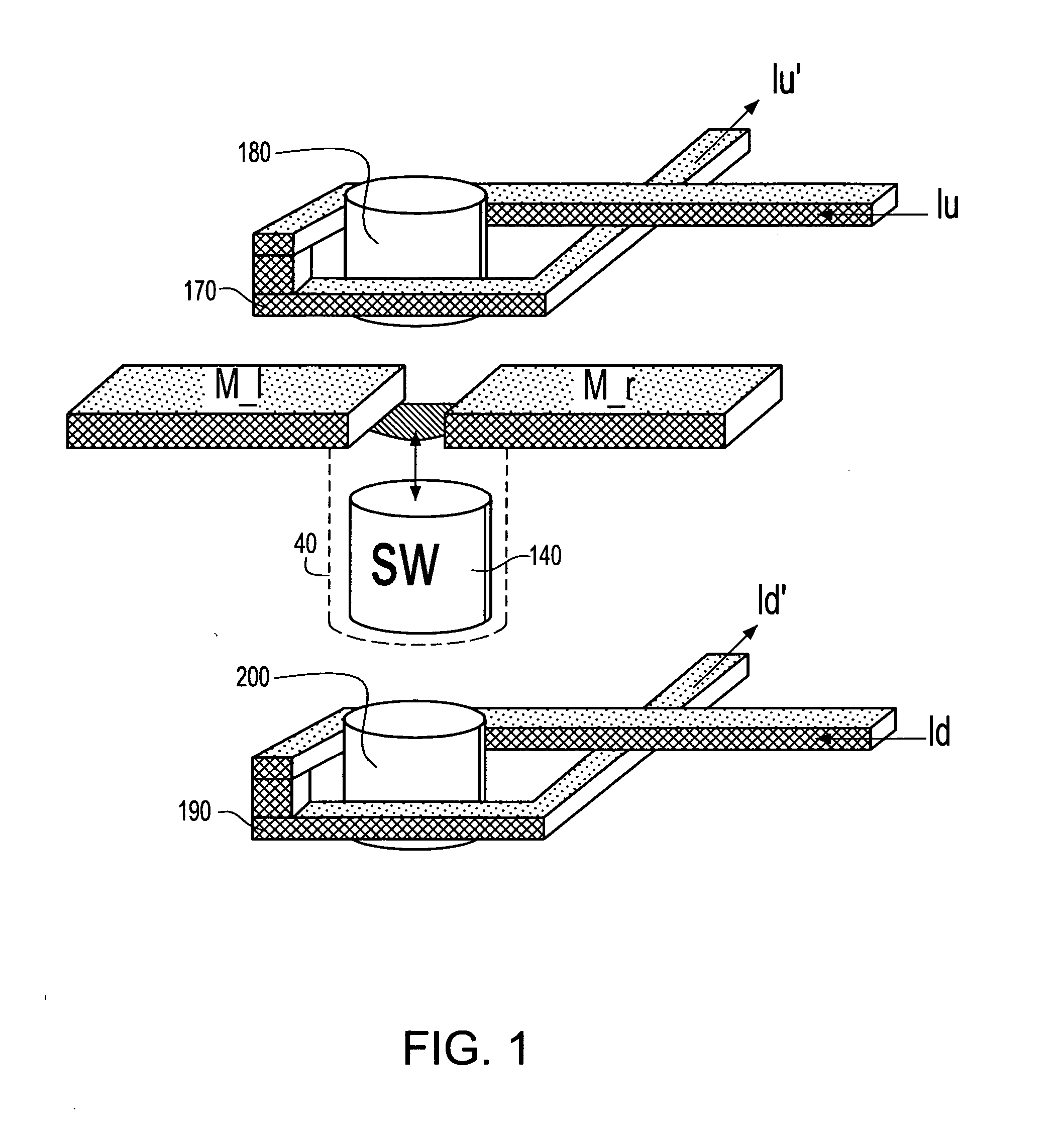
[0033]FIG. 1 is a schematic diagram showing a perspective view of MC-MEM switch of the present invention.
[0034] The MC-MEMS is illustrated showing the following basic elements: (1) an upper inductive coils 170, an optional lower inductive coil 190; (2) an upper a core 180, an optional lower core 200 preferably made of permalloy, (3) a micro-cavity 40, and (4) a switching element 140 freely moving therein (hereinafter SW) preferably made of magnetic material. Switching is activated by passing a current (Iu) through the upper coil, inducing a magnetic field in the coil element 170. In such an instance, the lower coil 190 is disabled (no current passes through the lower coil, i.e., Id=0). The magnetic field attracts the free-moving magnetic element 140 upwards, shorting the two individual wire segments M_1 and M_r. When the current flow stops or is reversed, the free-moving magnetic element 140 drops back by gravity to the bottom of the micro-cavity, opening the wire and turning off t...
PUM
| Property | Measurement | Unit |
|---|---|---|
| Diameter | aaaaa | aaaaa |
| Height | aaaaa | aaaaa |
| Diameter | aaaaa | aaaaa |
Abstract
Description
Claims
Application Information