Automotive grease gun

a grease gun and automotive technology, applied in the direction of manual lubrication, instruments, volume meters, etc., can solve the problems of inability to adapt to adjust biasing pressure, prior art suffers from relatively high friction mechanisms and disregard for need, and prior art fluid ejection tools are too often too delicate in mechanical design, etc., to achieve high reliability and durability, low cost, and efficient and effective

Inactive Publication Date: 2006-12-14
ZHANG LING
View PDF11 Cites 6 Cited by
  • Summary
  • Abstract
  • Description
  • Claims
  • Application Information

AI Technical Summary

Benefits of technology

[0019] A principal objective of the present invention is to provide a portable grease gun that will have a power source, e.g., rechargeable battery, and with a fluid pumping mechanism in the form of a more efficient and effective pump plunger drive system. This system includes a low friction eccentric pin uniquely engaging a stable, robust spring biased plunger-holding device, so as to ensure a highly dependable and durable, yet relatively low cost, system.

Problems solved by technology

The plug serves to secure the check valve assembly in place, but is not adapted to adjust biasing pressure of the spring.
In particular, and despite many years of incremental development in this field, the prior art suffers from relatively high friction mechanisms and a disregard for the need for important adjustability features to ensure smooth and ready delivery of fluid on demand.
Additionally, prior art fluid ejection tools too often are far too delicate in mechanical design.
Specifically, their point of failure most often lies in the mechanism for transferring rotary motion of reduction gearing to linear motion of the fluid ejection piston or plunger.
This is especially a problem in ejection tools where no adjustment means is available to the user to accommodate field conditions.

Method used


Image

  • Automotive grease gun
  • Automotive grease gun
  • Automotive grease gun

Examples


Embodiment Construction

[0039] It should be appreciated that the tool described as the present invention can have a number of applications, and that reference to grease gun or grease fluid is merely an economy of expression in the interest of efficiency and brevity. Thus, this reference in the title and description is without intent to limit the invention scope or in any respect to exclude equivalents.

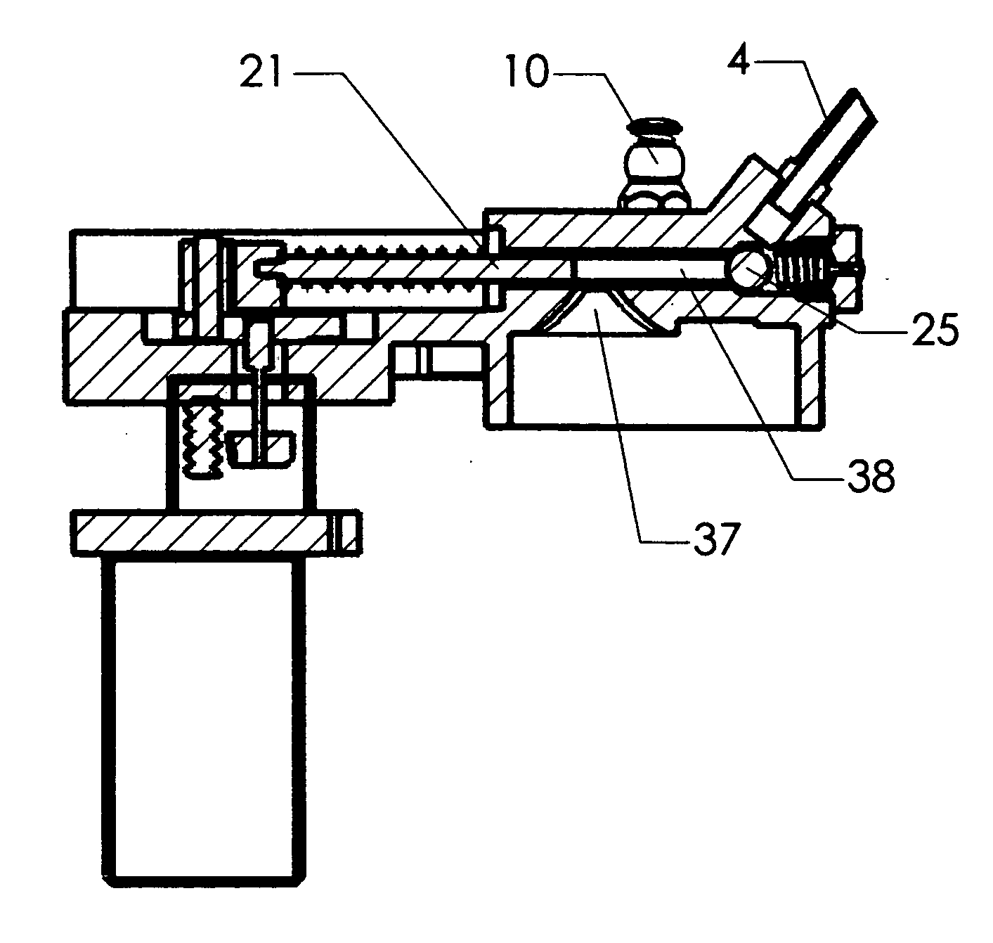
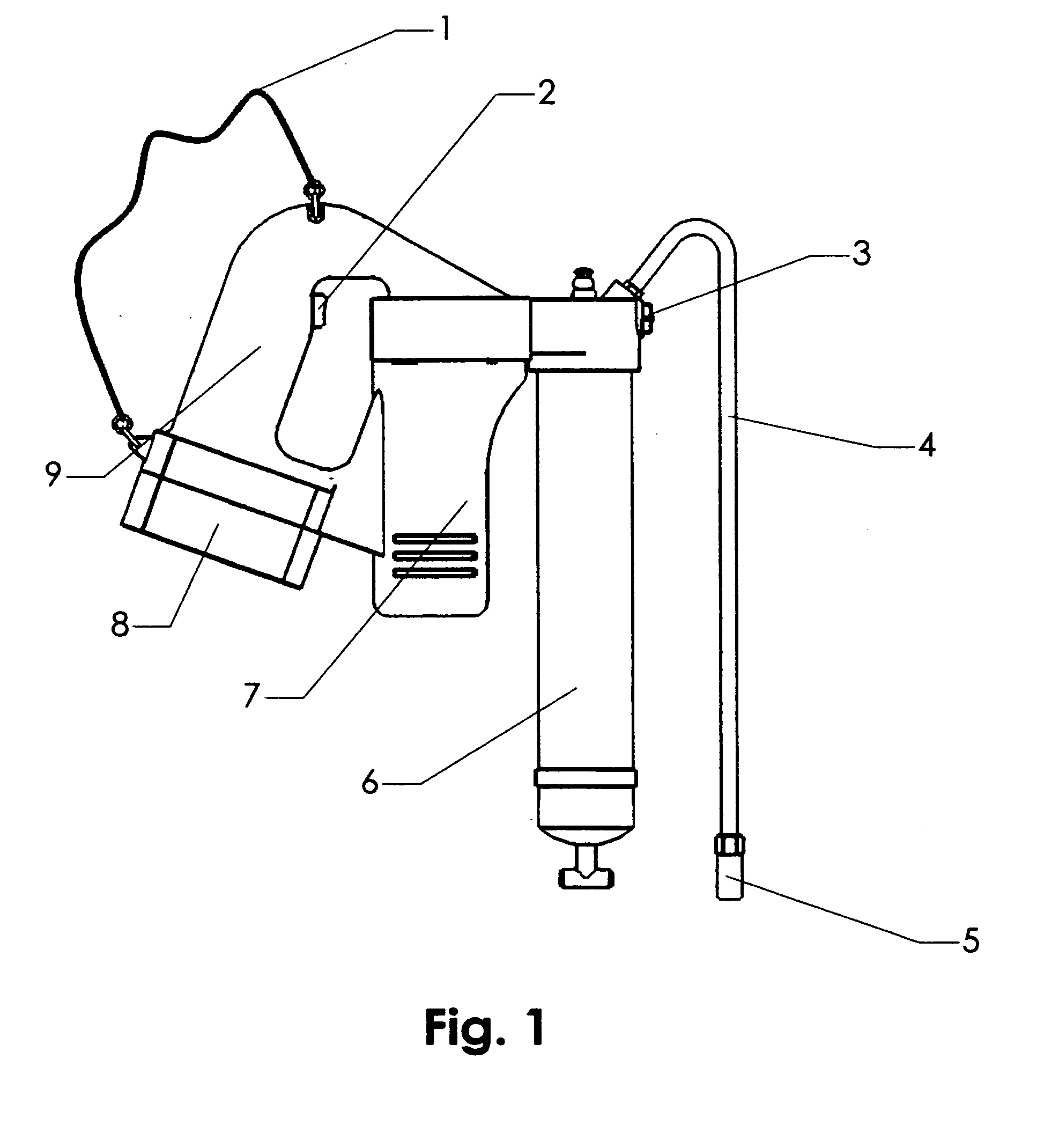
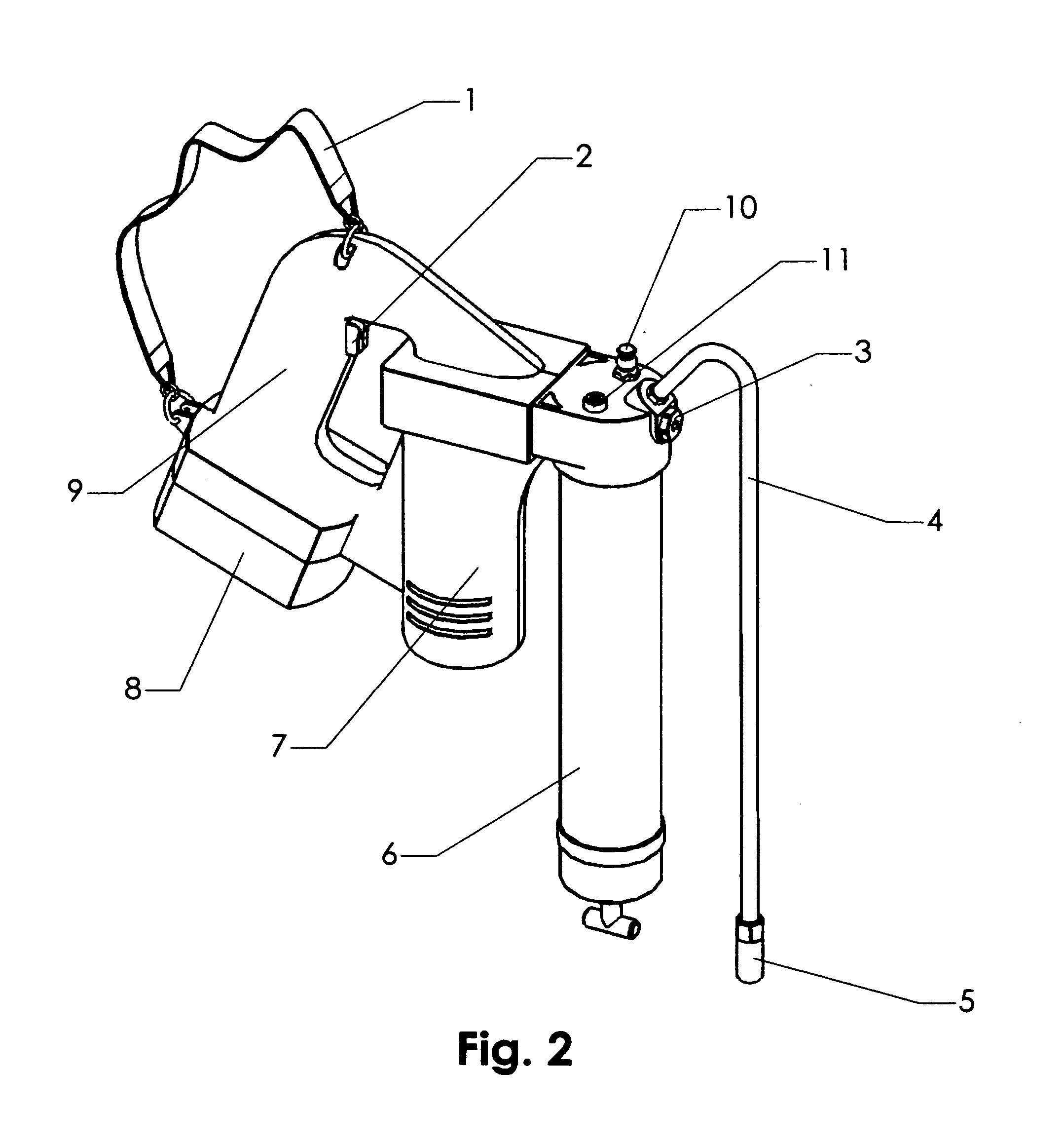
[0040] In terms of an operating system, the present invention includes four main work portions. Viewing FIG. 1, it is apparent that these main portions include a handle grip 9 a power supply, along with a power and transmission system shown generally at 7, fluid (e.g., grease) supply source or container 6 and tool output conduit 4. The handle grip 9 further includes an on-off switch 2.

[0041] To accommodate tool weight and backpressure forces during fluid delivery, an auxiliary shoulder belt or strap 1 is suitably attached to the handle grip 9. Extended periods of wielding such a portable device can be exhau...


PUM


Abstract

A shoulder supported, hand directed automotive grease gun in which a reciprocating piston transfers fluid from a supply tube to an outlet conduit. A battery powered motor and gear transmission rotate a disc on which is mounted an eccentric pin. The pin forcibly moves a piston holder between low friction parallel guides so as to advance the piston with its transferred fluid toward the outlet conduit. A first spring constantly biases the piston holder toward the pin so that the piston reciprocates rapidly as the disc rotates. An adjustable spring-loaded ball seal unit with an adjustable spring seat controls flow of the fluid. A fluid supply tube heating device alters fluid density to also control fluid flow. An auxiliary shoulder strap relieves pressure on an operator's wrist and transfers backpressure and tool weight to the operators body.

Description

REFERENCE TO RELATED APPLICATIONS [0001] Not applicable REFERENCE TO SEQUENCE LISTING [0002] Not applicable BACKGROUND OF THE INVENTION [0003] 1. Field of the Invention [0004] The invention disclosed and claimed herein relates to battery powered, hand manipulated fluid dispensing tools of the type typically referred to as grease guns, and more particularly to a cam and piston fluid ejection system acting against an adjustable check valve to control output. [0005] 2. Description of the Related Art [0006] Hand manipulated fluid dispensers of the type employed as grease guns and the like generally include fluid pumps driven by power transmission systems including DC motors and associated power output gearing systems. Typically, as a final power transmission segment, a reciprocating piston or plunger interconnected to or engaged by the power transmission system acts in a first direction along a passageway to rapidly eject fluid, e.g., grease. The fluid exits by force through an outlet a...

Claims


Application Information

Patent Timeline
Patent Type & Authority Applications(United States)
IPC IPC(8): G01F11/00
CPCF16N3/12G01F11/022F16N9/04
Inventor ZHANG, LING
Owner ZHANG LING
Why Eureka
Try Eureka