Electrosurgical pencil

a technology of electronic pencils and pencils, applied in the field of electronic surgical pencils, can solve the problems of destroying tissue, compromising the hermetic seal provided, and leaving voids between the two housing parts

Inactive Publication Date: 2002-03-26
MEDTREX
View PDF22 Cites 105 Cited by
  • Summary
  • Abstract
  • Description
  • Claims
  • Application Information

AI Technical Summary

Problems solved by technology

Since the blade is relatively small relative to the ground plate, the energy being transferred to the patient through the small blade is concentrated such that the high frequency causes tissue destruction.
The hollow configuration, ultrasonic welding and the rigid construction of the prior art pencils all provide for a series of problems.
The use of an ultrasonic assembly for ultrasonic welding may still leave voids between the two housing parts and compromise the hermetic seal provided.
Additionally, the rigid plastic housing does not provide any stress relief for the cable which connects the pencil housing to the electrosurgical generator.
Consequently, the rigid plastic housings increase the likelihood of a break in the cable (i.e., wire fatigue) at the point where the cable enters the pencil housing.
A further problem with the prior art housings is that they do not accommodate changes in the blade positioning.
However, the bending of the blade itself is undesirable since the blade can reach relatively high temperatures, and touching the blade itself can be dangerous to the user and may contaminate the electrosurgical pencil.

Method used


Image

  • Electrosurgical pencil
  • Electrosurgical pencil
  • Electrosurgical pencil

Examples


Embodiment Construction

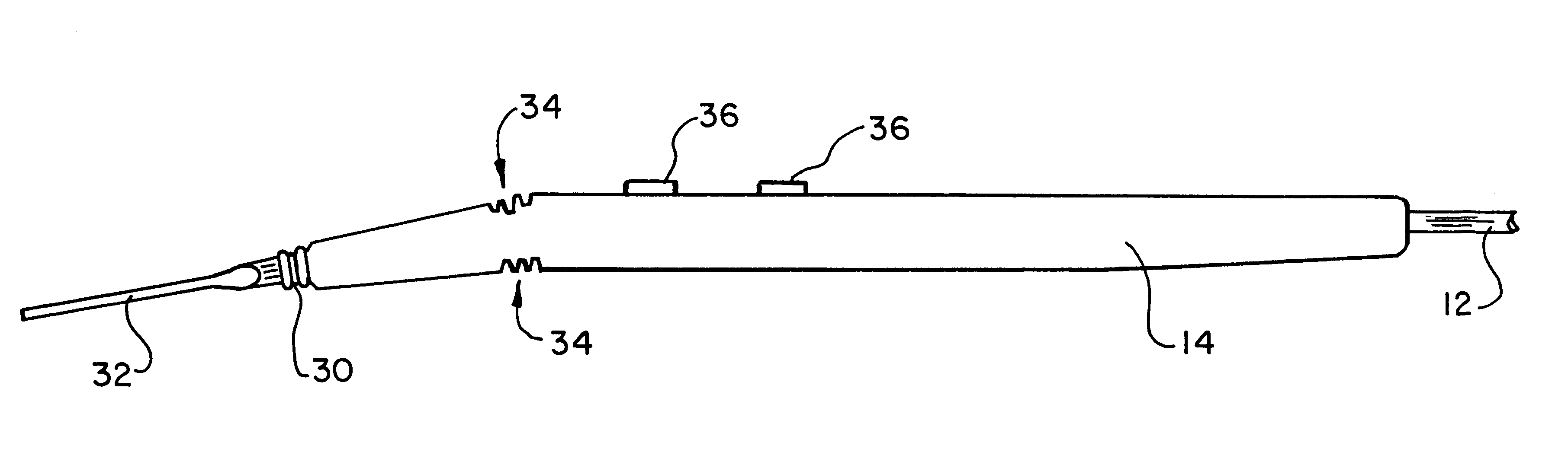
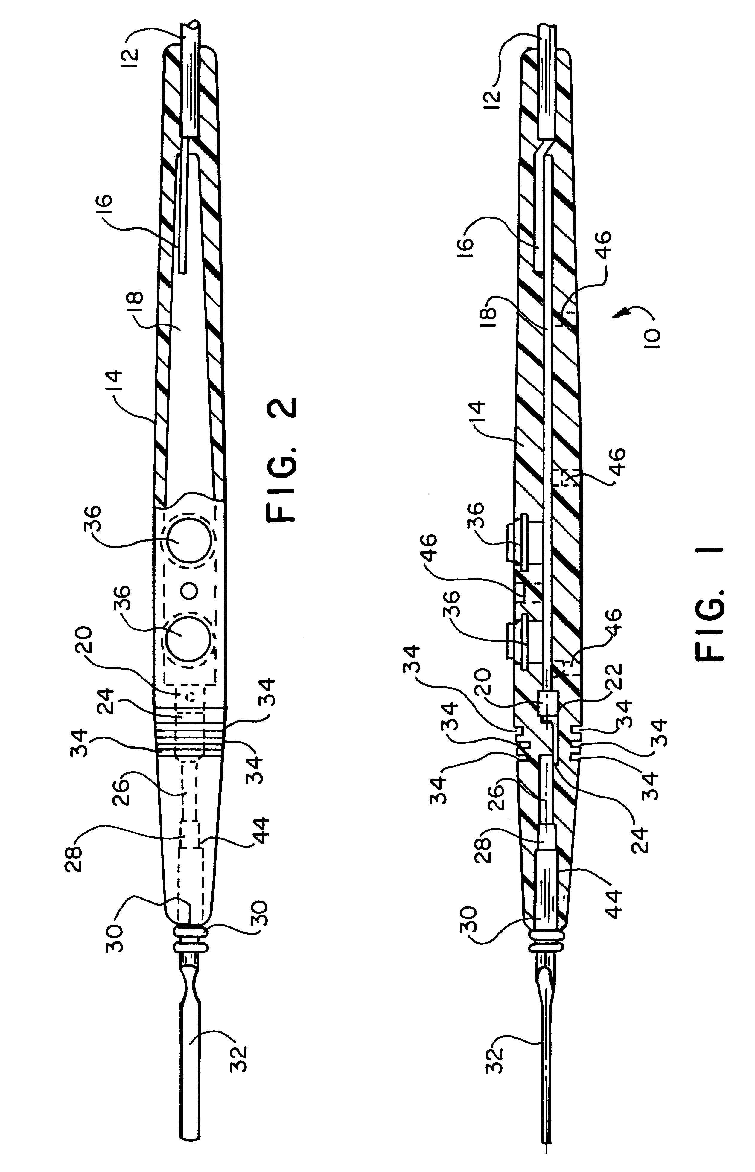
FIGS. 1-6 illustrate a hand controlled electrosurgical pencil 10 according to the present invention. The pencil 10 includes an insulated cable 12 which is connectable with an electrosurgical generator (not shown) in a known manner such as with a three-prong plug. The cable 12 is received within a first end of a pencil housing 14 as best shown in FIGS. 1 and 2. Leads 16, shown schematically in FIGS. 1 and 2, of the cable 12 are attached to appropriate portions of a printed circuit board switch 18. The switch 18 is preferably formed with a rigid body to provide a certain amount of rigidity to the pencil housing 14 as will be described hereinafter.

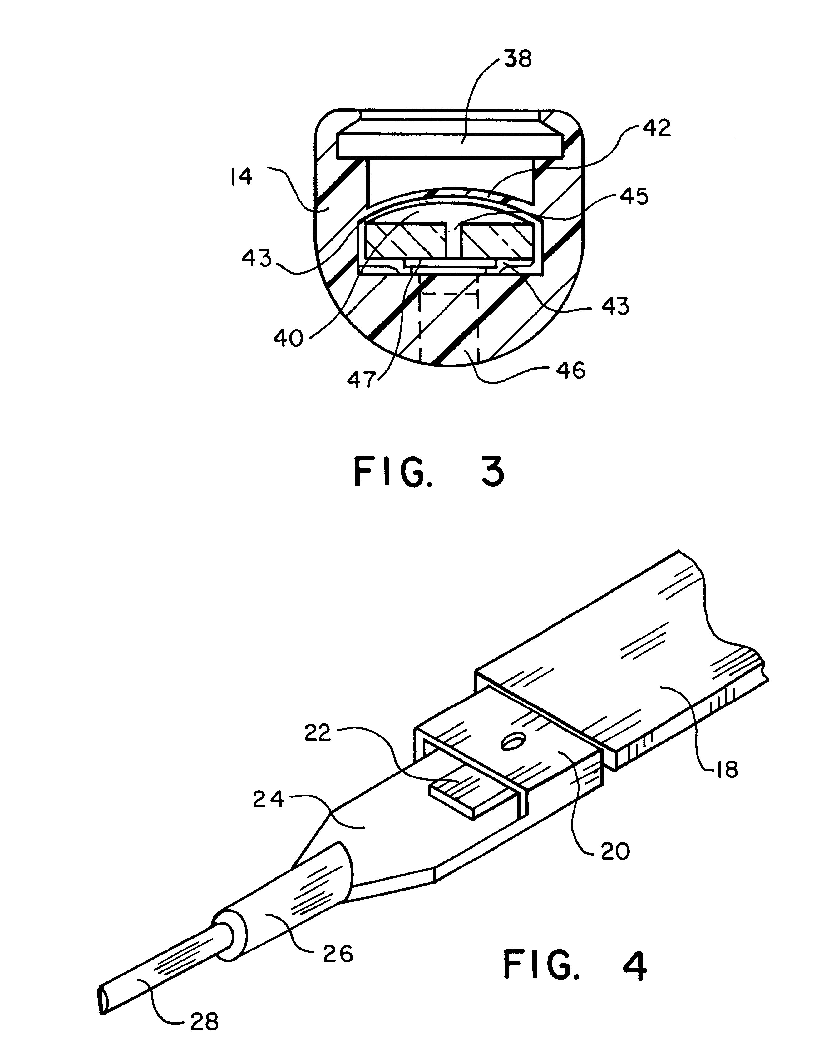
An attachment end 20 of a metal collet is crimped or otherwise secured to a lead 22 of the switch 18. This connection is schematically illustrated in FIG. 4. The metal collet includes a flat portion 24 extending from the attachment end 20 to a cylindrical blade electrode receiving socket 26.

A round connecting lead 28 of a blade electrode is r...


PUM


Abstract

An electrosurgical pencil for delivering high frequency cutting and coagulation signals from an electrosurgical generator is disclosed. A flexible, elongated, substantially solid pencil housing is provided having a cable receiving end and a blade electrode receiving end opposed from the cable receiving end. A mechanism is provided within the pencil housing for bending of the pencil housing between the cable receiving end and the blade electrode receiving end. Additionally, a mechanism is provided within the electrosurgical pencil for retaining a bent position of the pencil housing. The electrosurgical pencil of the present design may be a foot controlled electrosurgical pencil or may include a manually actuated switch within the pencil housing to form a hand controlled electrosurgical pencil.

Description

1. Field of the InventionThe present invention relates to electrosurgical hand controlled and foot controlled pencils. More specifically, the present invention relates to an electrosurgical pencil having a flexible, substantially solid pencil housing.2. Prior ArtIn electrosurgical techniques using electrosurgical pencils, an electrosurgical generator generates current in a particular wave form upon demand, and the current is carried to an electrosurgical pencil having a relatively small blade. The current is transmitted through the blade to the patient and back to the generator through a ground plate attached to the patient. Since the blade is relatively small relative to the ground plate, the energy being transferred to the patient through the small blade is concentrated such that the high frequency causes tissue destruction. Typically, such devices have two modes of operation, cutting and coagulation, which require current having different wave forms.In hand controlled electrosurg...

Claims


Application Information

Patent Timeline
Patent Type & Authority Patents(United States)
IPC IPC(8): A61B18/14
CPCA61B18/1402A61B2018/1253
Inventor BUREK, PAUL P.
Owner MEDTREX
Why Eureka
Try Eureka