Electrophotographic photoreceptor, and image forming apparatus and process cartridge therefor using the electrophotographic photoreceptor

a photoreceptor and electrophotography technology, applied in the field of electrophotographic photoreceptors, can solve the problems of deterioration of image density and image gradation in affecting the quality and requiring replacement, so as to prevent the production of negative and positive images with background fouling and increase residual potential , the effect of high durability and stability

Inactive Publication Date: 2009-03-24
RICOH KK
View PDF82 Cites 5 Cited by
  • Summary
  • Abstract
  • Description
  • Claims
  • Application Information

AI Technical Summary

Benefits of technology

[0034]Accordingly, one object of the present invention is to provide a highly durable and stable electrophotographic photoreceptor preventing production of images having background fouling and increase of residual potential.

Problems solved by technology

However, a photoreceptor having a smaller diameter naturally has less durability and needs to be replaced earlier.
The background fouling is an image defect of innumerable microscopic spots developed on the blank area.
Although the background fouling is not actualized when the photoreceptor is new, the photoreceptor fatigue (poorly-charged photoreceptor) due to repeated use or the increase of the electric field intensity due to abrasion of the photosensitive layer actualize the background fouling which is one of large factors determining a life of the photoreceptor.
However, these intermediate layers including a resin alone has high electric resistivities, and therefore the residual potential increases, resulting in occasional deterioration of image density and image gradation in negative and positive images.
However, these resin intermediate layers alone occasionally have problems of producing moire images due to light interference in recent image forming apparatus using coherent light such as a laser beam.
Therefore, it is very difficult to reduce both of the residual potential and background fouling.
However, it is ineffective to prevent moire images from being produced even when a filler is dispersed in the undercoat layer or intermediate layer, and even a filler-dispersed layer occasionally increases the residual potential.
However, only the optional resin layer prevents a charge from being injected into the photosensitive layer from the electroconductive substrate, and therefore it cannot be said that this fully prevents the background fouling.
However, this does not fully achieve the high durability, either.
Only the higher abrasion resistance of a photoreceptor is not sufficient enough to decrease the charge injection from an electroconductive substrate because the charge injection is increased by the charge deterioration of a photoreceptor due to the fatigue thereof, although decreasing an influence of the electric field intensity as time passes.
However, (i) tends to increase residual potential and deteriorate image density because of poor compatibility of the hardening binder with a charge transport material, and impurities such as a polymerization initiator and an unreacted residue.
(ii) does not fully satisfy the durability required for an organic photoreceptor.
In addition, a high-purity charge transport polymer material is difficult to obtain because it is difficult to polymerize and refine the materials.
Further, a coating liquid including the charge transport polymer material occasionally has a high viscosity, resulting in a problem of preparing a photoreceptor.
(iii) also tends to increase residual potential and deteriorate image density due to a charge trap present on the surface of the inorganic filler.
However, a three-dimensional network is not fully developed and the crosslinking density is low in the photoreceptor because a monomer is reacted therein including a polymer binder, resulting in insufficient abrasion resistance thereof.
However, a three-dimensional network is not fully developed, either and the crosslinking density is low in the photoreceptor, resulting in insufficient abrasion resistance thereof.
However, the photosensitive layer tends to have a surface crack or peel-off.

Method used


Image

  • Electrophotographic photoreceptor, and image forming apparatus and process cartridge therefor using the electrophotographic photoreceptor
  • Electrophotographic photoreceptor, and image forming apparatus and process cartridge therefor using the electrophotographic photoreceptor
  • Electrophotographic photoreceptor, and image forming apparatus and process cartridge therefor using the electrophotographic photoreceptor

Examples


example 1

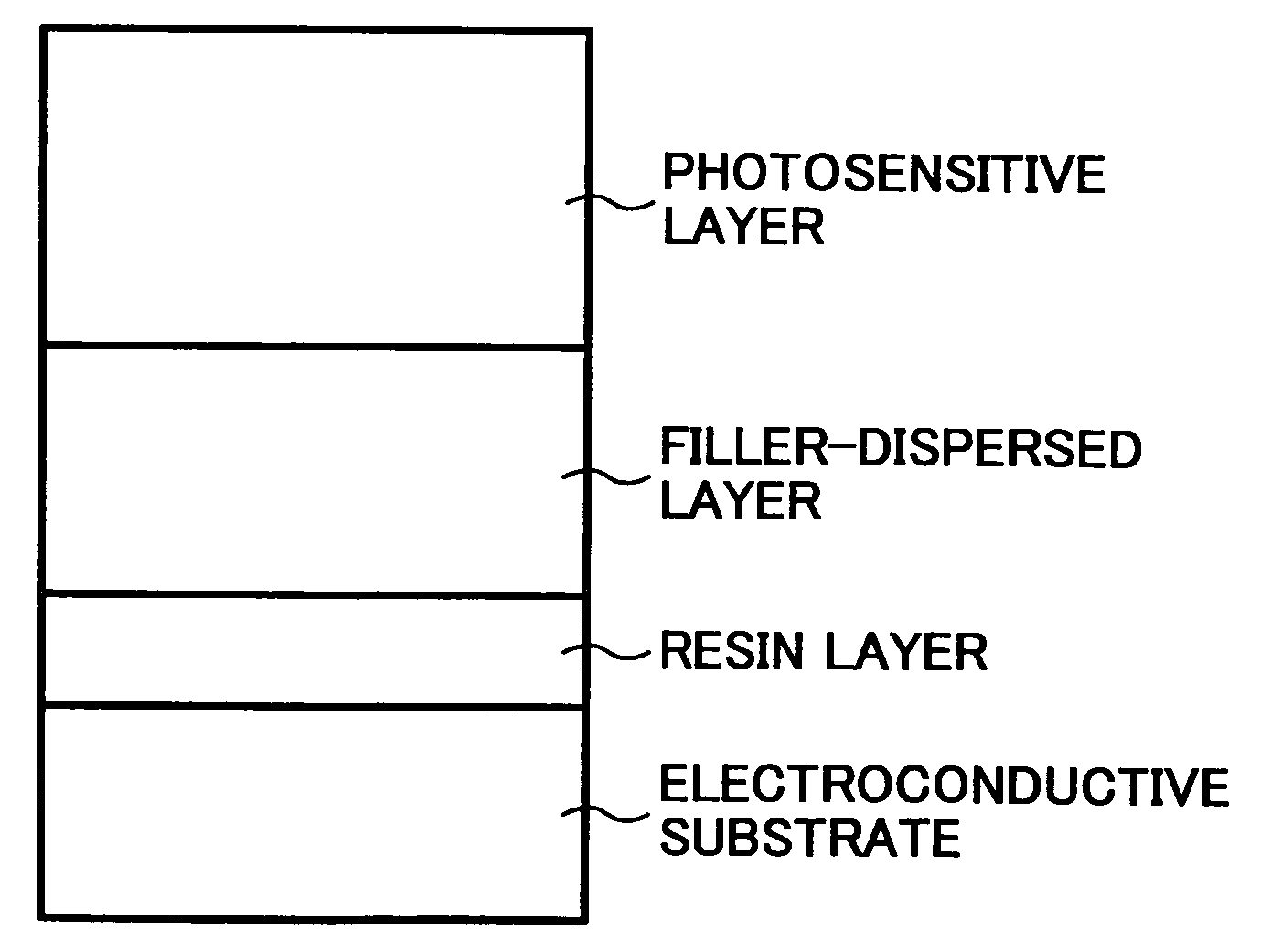
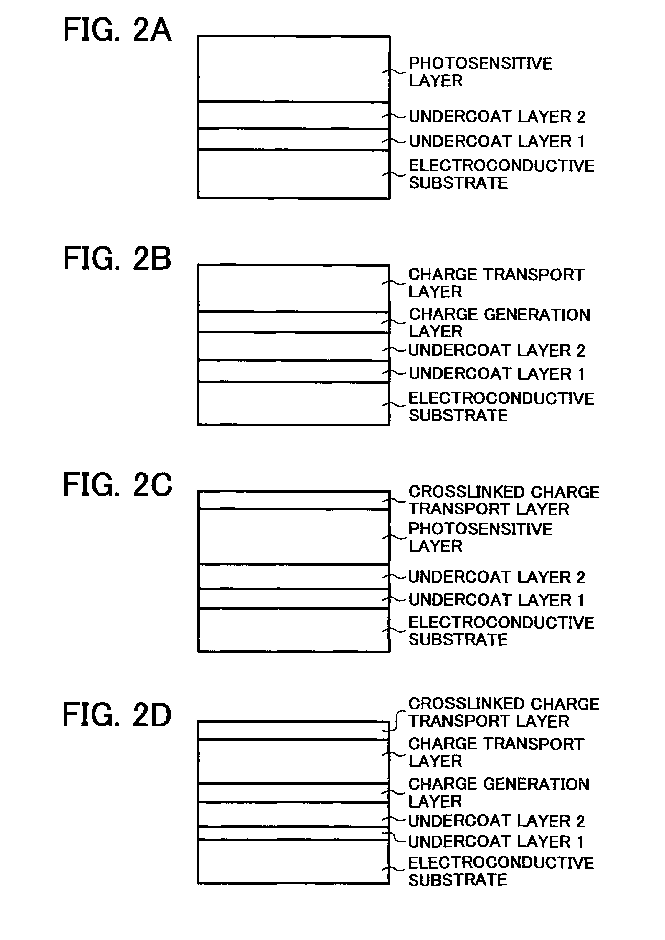
[0237]An undercoat layer 1 coating liquid 1, an undercoat layer 2 coating liquid, a CGL coating liquid and a CTL coating liquid having the following formulations were coated and dried in this order on an aluminium cylinder having a diameter of 100 mm to prepare an electrophotographic photoreceptor 1 having an undercoat layer 1 0.7 μm thick, an undercoat layer 2 and a CGL of 3.5 μm thick, and a CTL of 28 μm thick. Each layer was dried to the touch after coated, and further dried with heat at 130, 140, 90 and 135° C. respectively.

Undercoat Layer 1 Coating Liquid

[0238]

N-methoxymethylated nylon5(FR101 from Namariichi Co., Ltd.)Methanol70n-butanol30

Undercoat Layer 2 Coating Liquid

[0239]

Titanium oxide70(CR-EL from Ishihara Sangyo Kaisha, Ltd.,having a purity of 99.7%, an average primaryparticle diameter about 0.25 μm and specificresistivity of 3.5 × 10⁹ Ω· cm)Alkyd resin14(Bekkolite M6401-50 fromDainippon Ink And Chemicals, inc.,having a solid content of 50% anda hydroxyl value of 130)Blo...

example 2

[0243]The procedure for preparation of the electrophotographic photoreceptor 1 in Example 1 was repeated to prepare an electrophotographic photoreceptor 2 except for replacing the undercoat layer 2 coating liquid with a coating liquid having the following formulation.

Undercoat Layer 2 Coating Liquid

[0244]

Titanium oxide80(CR-EL from Ishihara Sangyo Kaisha, Ltd.,having a purity of 99.7%, an average primaryparticle diameter about 0.25 μm and specificresistivity of 3.5 × 10⁹ Ω· cm)Alkyd resin12(Bekkolite M6163-60 fromDainippon Ink And Chemicals, inc.,having a solid content of 60% anda hydroxyl value of 70)Block isocyanate resin10(Burnock B3-867 fromDainippon Ink And Chemicals, inc.,having a solid content of 70%)2-butanone100

[0245]The metal oxide to the alkyd resin is about 1.9 / 1 in content ratio. The alkyd resin to the block isocyanate resin is about 1 / 1 in weight ratio.

example 3

[0246]The procedure for preparation of the electrophotographic photoreceptor 1 in Example 1 was repeated to prepare an electrophotographic photoreceptor 3 except for replacing the undercoat layer 2 coating liquid with a coating liquid having the following formulation.

Undercoat Layer 2 Coating Liquid

[0247]

Zinc oxide80(SAZEX 2000 fromSAKAI CHEMICAL INDUSTRY CO., LTD.,having a purity of 99.8%, an average primaryparticle diameter about 0.6 μm and specificresistivity of 5.4 × 10⁷ Ω· cm)Alkyd resin20(Bekkolite M6401-50 fromDainippon Ink And Chemicals, inc.,having a solid content of 50% anda hydroxyl value of 130)Block isocyanate resin10(Burnock B7-887-60 fromDainippon Ink And Chemicals, inc.,having a solid content of 60%)2-butanone100

[0248]The metal oxide to the alkyd resin is about 1.3 / 1 in content ratio. The alkyd resin to the block isocyanate resin is about 1.7 / 1 in weight ratio.


PUM

PropertyMeasurementUnit
specific resistivityaaaaaaaaaa
thicknessaaaaaaaaaa
specific resistivityaaaaaaaaaa

Abstract

An electrophotographic photoreceptor, including:an electroconductive substrate;a first undercoat layer including no metal oxide, located overlying the electroconductive substrate;a second undercoat layer including a metal oxide and a binder resin, located overlying the first undercoat layer; anda photosensitive layer located overlying the second undercoat layer,wherein the metal oxide included in the second undercoat layer has a specific resistivity not less than 107 Ω·cm and a block isocyanate compound.

Description

BACKGROUND OF THE INVENTION[0001]1. Field of the Invention[0002]The present invention relates to an electrophotographic photoreceptor, and to an image forming apparatus and a process cartridge therefor using the electrophotographic photoreceptor.[0003]2. Discussion of the Background[0004]Recently, information processing systems using electrophotographic methods have noticeably been developed. Particularly, laser printers and digital copiers converting information to digital signals and optically recording the information have remarkably been improved in their printing qualities and reliabilities. These laser printers and digital copiers rapidly prevailing are required to print at higher speed and downsize as well as to produce higher quality images. Further, demands for full-color laser printers and full-color digital copiers capable of printing full-color images are rapidly increasing. At least four toner images having different colors each other need to be overlapped to form a ful...

Claims


Application Information

Patent Timeline
Patent Type & Authority Patents(United States)
IPC IPC(8): G03G15/04
CPCG03G5/043G03G5/0546G03G5/0589G03G5/0592G03G5/071G03G5/142G03G5/144G03G5/072G03G5/0732G03G5/074G03G5/0745
Inventor TAMOTO, NOZOMUNIIMI, TATSUYAKOEDA, MAIKOSUZUKI, TETSUROKINOSHITA, TAKEHIKONOZOE, SUZUKAOHTA, KATSUICHI
Owner RICOH KK
Why Eureka
Try Eureka