Coated print roll and method therefor

Inactive Publication Date: 2009-12-10
BARR GEORGE A +3
View PDF6 Cites 6 Cited by
  • Summary
  • Abstract
  • Description
  • Claims
  • Application Information

AI Technical Summary

Benefits of technology

[0004]Accordingly, it is an object of the inv

Problems solved by technology

Print rolls and metering rolls are subject to mechanical wear, foreign substances, mois

Method used


Image

  • Coated print roll and method therefor
  • Coated print roll and method therefor
  • Coated print roll and method therefor

Examples


Embodiment Construction

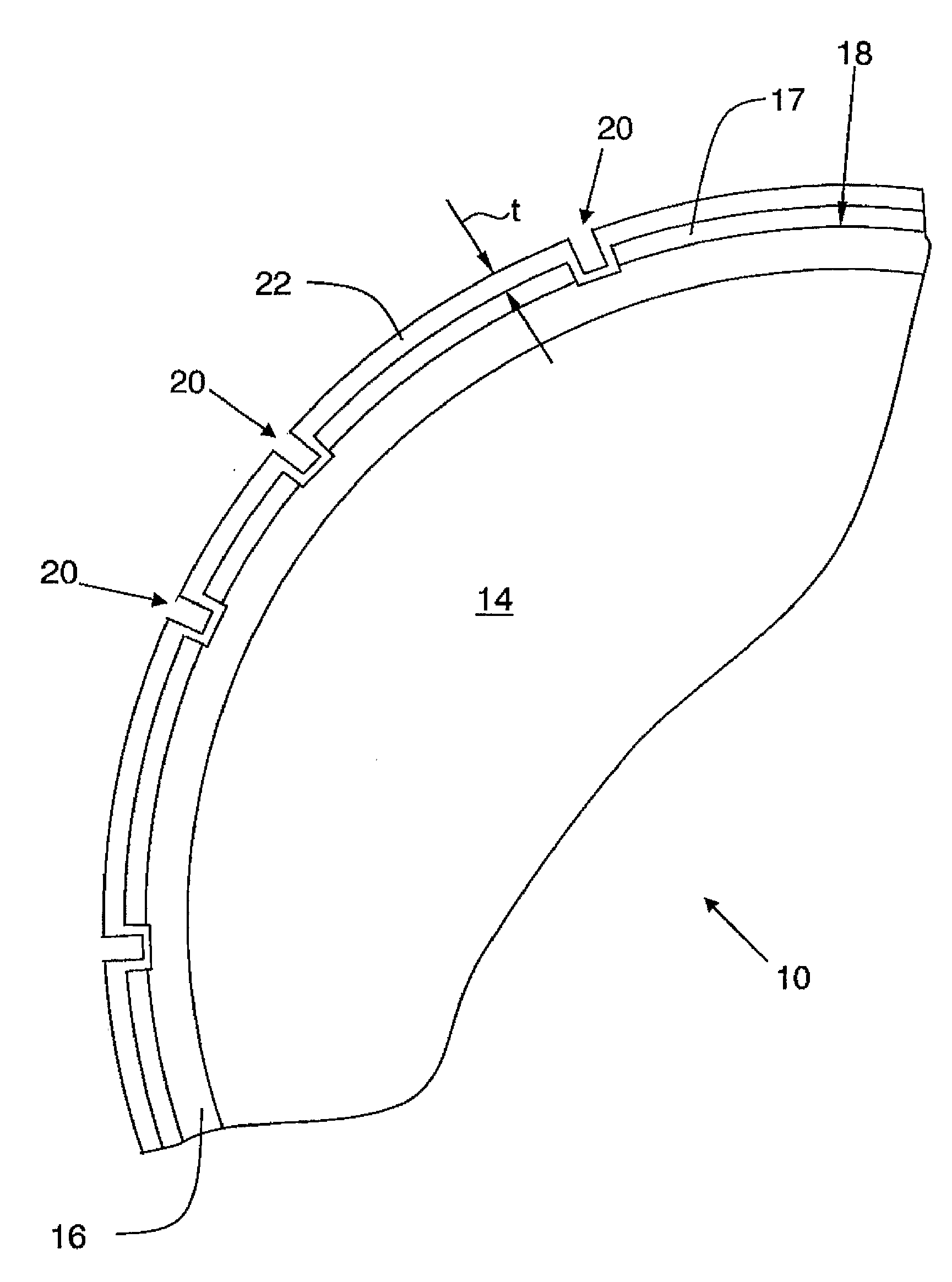
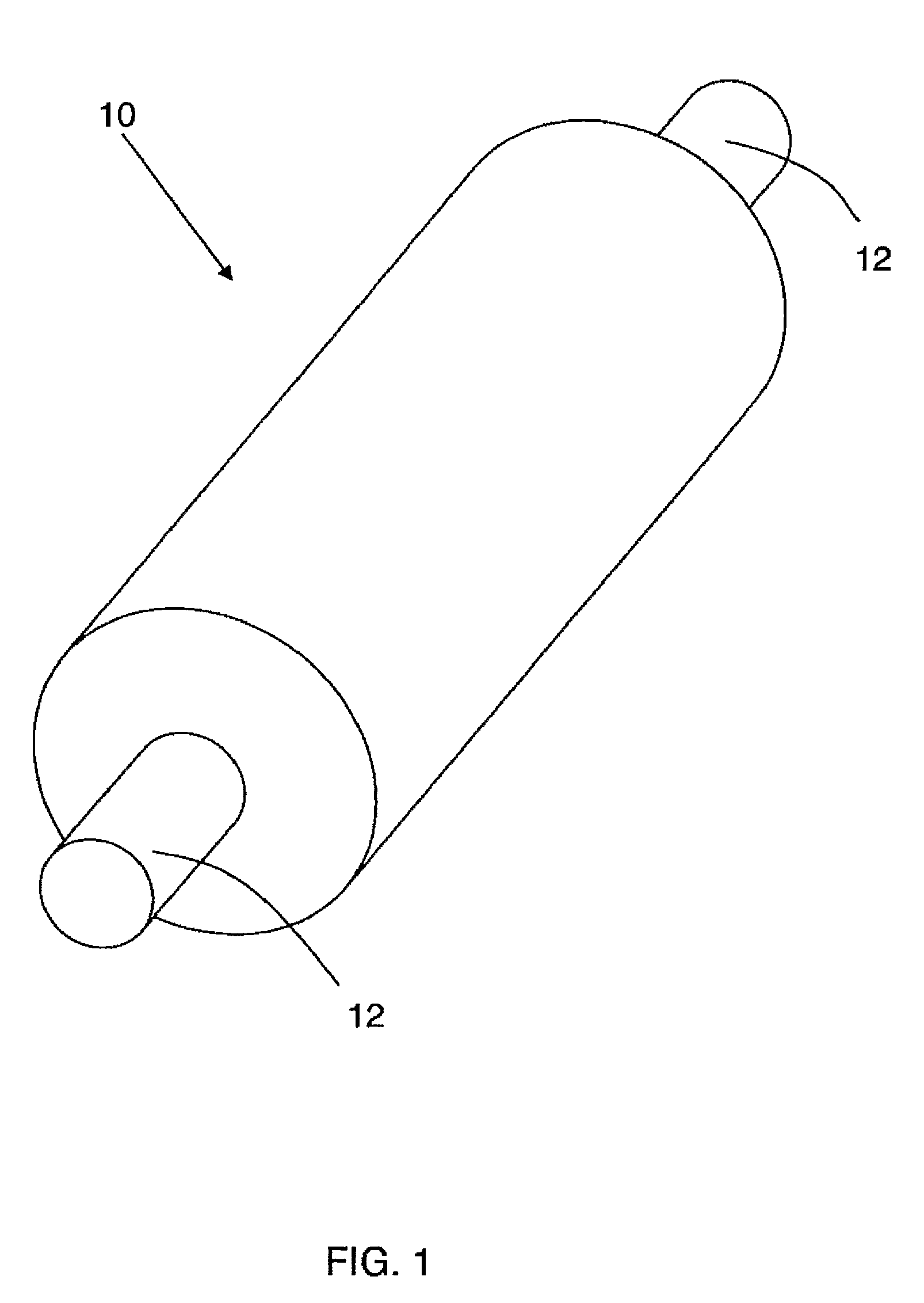
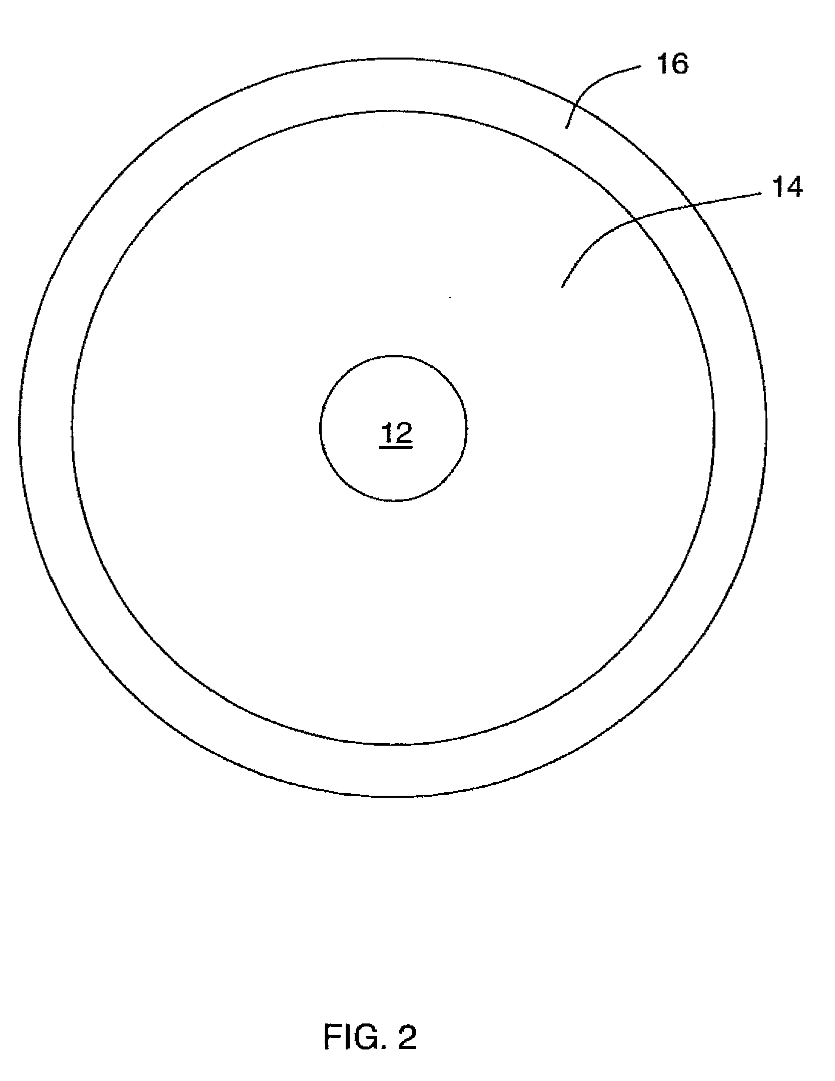
[0017]Referring to the drawings wherein identical reference numerals denote the same elements throughout the various views, FIGS. 1-3 depict an exemplary print roll 10 constructed in accordance with the present invention. As used herein, the term “print roll” is used to refer generally to any roll-like component of printing machinery used to hold, transfer, meter, or apply ink, varnish, or other fluids. The print roll 10 is generally cylindrical and has opposed ends with mounting shafts or other fixation means 12. In the illustrated example, the print roll 10 has a core 14 with a relatively thin facing layer 16 disposed thereon. The facing layer 16 may be metallic, for example a steel or copper alloy, and may be applied through a plating process. Other materials such as ceramics, plastics, polymers, elastomers, or resins may also be used for the facing layer 16. The print roll 10 could also be of solid construction, for example steel, aluminum, or copper alloy, without the facing la...


PUM


Abstract

A print roll has opposed ends and a generally cylindrical print surface, and a carbon-based thin film having an amorphous microstructure disposed on the print surface. The thin film may have multiple layers and may be applied by plasma assisted chemical vapor deposition.

Description

BACKGROUND OF THE INVENTION[0001]This invention relates generally to wear coatings and surface treatments and their manufacture, and more particularly to a method for applying wear treatment to printing rolls.[0002]Printing processes are often carried out using cylindrical “print rolls”. These are metallic rolls with ink pockets formed therein, and are used for processes such as transferring an ink image directly to a substrate, or transferring fluid media (e.g., ink, varnish) from one step in a printing process to another (e.g. as a “metering roll”) via transfer pockets.[0003]Print rolls and metering rolls are subject to mechanical wear, foreign substances, moisture, and chemical attack. All of these hazards reduce the useful life of the print roll.BRIEF SUMMARY OF THE INVENTION[0004]Accordingly, it is an object of the invention to provide a highly durable print roll.[0005]It is another object to provide a method for method for coating a print roll.[0006]It is yet another object of...

Claims


Application Information

Patent Timeline
IPC IPC(8): B41F11/00
CPCB41F31/26B41M1/10B41N1/22B41N1/16B41M2205/12
Inventor BARR, GEORGE A.KELLAR, FRANZ W.FAULKNER, DONALD G.SIEGENTHALER, WALTER
Owner BARR GEORGE A
Why Eureka
Try Eureka