Push switch

a push switch and switch technology, applied in the direction of emergency actuators, contact mechanisms, electrical devices, etc., can solve the problems of poor durability and reliability, lack of general-purpose versatility of the push switch, and risk of breaking, so as to achieve excellent durability and reliability, the effect of preventing excessive force from acting on the switch and improving the durability and reliability of the push switch

Inactive Publication Date: 2012-01-12
TOKYO PARTS IND CO LTD
View PDF1 Cites 5 Cited by
  • Summary
  • Abstract
  • Description
  • Claims
  • Application Information

AI Technical Summary

Benefits of technology

[0018]With the push switch of the present invention, the periphery of the main body part (32) of the switch (30) is surrounded by the cover portion (42), which is higher than the main body portion (32), whereby excessive force can be effectively prevented from acting on the switch, so as to produce a push switch having excellent durability and reliability. Furthermore, by using a mount (40) in which the base portion (41) on which the switch is mounted, the cover portion (42), which surrounds the periphery of the main body part of the switch, and the stopper portion (43) are integrally formed, the durability and reliability of the push switch can be improved without increasing the number of parts.
[0019]Furthermore, in the push switch of the present invention, if the corners at the top of the cover portion (42) are formed curved, and the cover portion (42) is formed with a space provided with respect to the inside of the button 20, it is possible to effectively prevent damage to the flexible button (20) which is pushed.

Problems solved by technology

With a push switch such as shown in FIG. 5, there is a problem in so much as, if the key top 114 is pushed with excessive force, it is possible that the elastic engagement member 113 will be damaged as a result of fissures resulting from undue elongation of the thin portions of the elastic engagement member 113, and as a result of the bottom face of the elastic engagement member 113 contacting the corners of the switch main body 112, so that the durability and reliability is inferior.
Furthermore, if the top key 114 is pushed with excessive force, an excessive force will act on the switch main body 112 and the switch board 116, and there is a risk of these breaking.
In addition, there were problems in that, because the button 121 and the switch case 126 are completely separated, the push switch lacks general-purpose versatility, and the production characteristics are inferior because, when this is mounted, it is necessary to align the button 121 and the switch case 126.

Method used


Image

  • Push switch
  • Push switch
  • Push switch

Examples


Embodiment Construction

[0026]Hereafter, embodiments of the present invention are described based on the drawings.

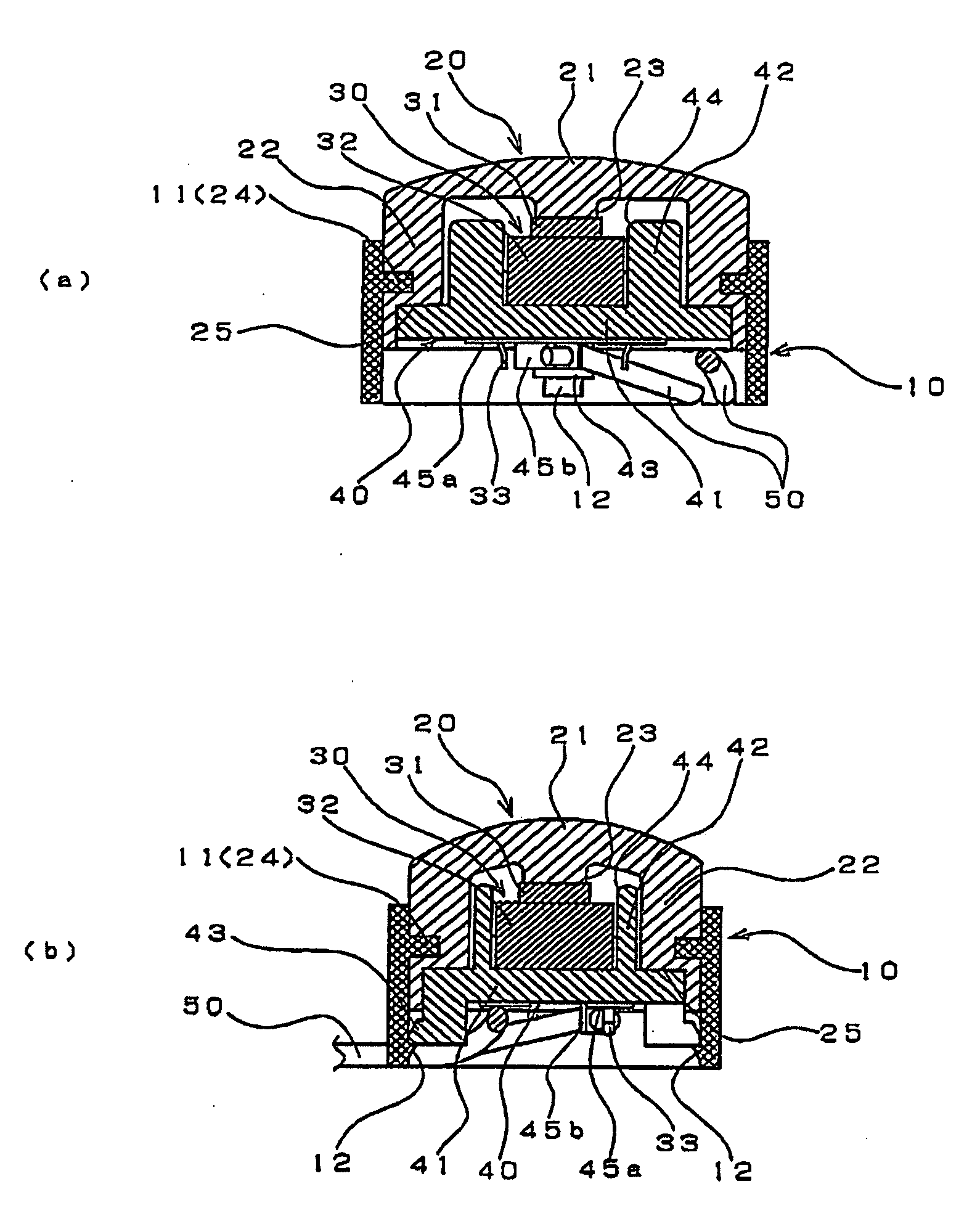
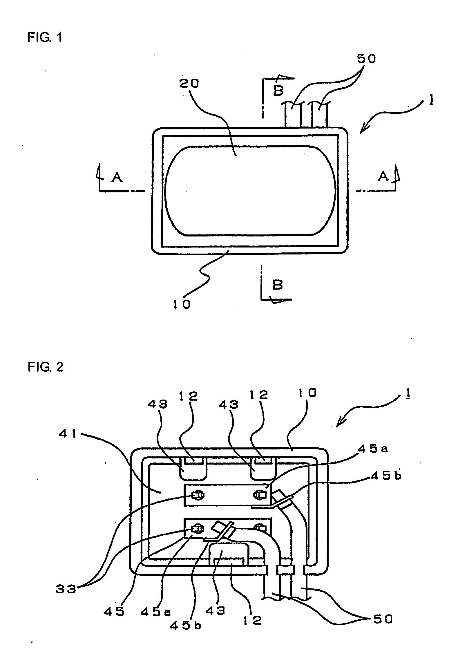
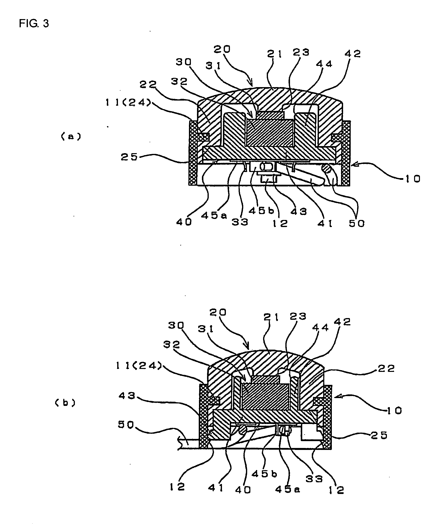
[0027]FIG. 1 to FIG. 3 show a push switch 1 according to one mode of embodiment of the present invention, wherein FIG. 1 is a top view, FIG. 2 is a bottom view, FIG. 3(a) is a sectional view along the line A-A in FIG. 1, and FIG. 3(b) is a sectional view along the line B-B in FIG. 1.

[0028]The push switch 1 of this example is mounted in a vehicle door handle device, which is not shown in the drawing. When a user operates a door lock device, a button 20 of the push switch 1 that is exposed by the vehicle door handle device is pushed, whereby the door can be locked or unlocked.

[0029]This push switch 1 comprises a case 10, a button 20, a switch 30, a mount 40, and lead wires 50.

[0030]The case 10 is integrally formed in a tubular shape from a hard resin, and has an engagement projection 11 at the upper interior, and latching claws 12 at the lower interior.

[0031]Note that the engagement projection 11...


PUM


Abstract

Disclosed is a push switch wherein a flexible button is fitted on top of a case which houses a switch that is disposed on a mount. The mount comprises, integrally formed from resin, a base portion on which the switch is mounted; a cover portion, which is formed higher than a main body part of the switch, on the top face of the base portion, and surrounds the periphery of the main body part; and a stopper portion, which is formed on the bottom face of the base portion, and latches on the inside of the case.

Description

BACKGROUND OF THE INVENTION[0001]1. Field of the Invention[0002]The present invention relates to a push switch using a flexible button.[0003]2. Description of the Related Art[0004]For example, Japanese Patent Laid-Open Publication No. 2009-146806 describes, as shown in FIG. 5, a push switch 110 comprising a base 111, a switch board 116 and a switch main body 112 disposed on the base 111, a key top 114 disposed on the switch main body 112, and a case 115, which houses the switch main body 112 so that a portion of the key top 114 protrudes, an elastic engagement member 113 being provided between the switch main body 112 and the key top 114, which is in close contact with the inner peripheral face of the case 115 and holds the key top 114.[0005]Furthermore, Japanese Patent Laid-Open Publication No. 2004-327126 describes a push switch for locking or unlocking a vehicle door which, as shown in FIG. 6, is fitted in an outside door handle 125 of a vehicle door lock device, wherein a switch...

Claims


Application Information

Patent Timeline
Patent Type & Authority Applications(United States)
IPC IPC(8): H01H13/14
CPCH01H2221/064H01H13/06E05B81/76H01H13/02H01H13/14H01H13/52
Inventor KITAHARA, TAKAHISAICHIMURA, ATSUSHI
Owner TOKYO PARTS IND CO LTD
Why Eureka
Try Eureka