Mounting pin and plughole arrangement

Active Publication Date: 2008-09-18
T CONN PRECISION CORP
View PDF8 Cites 6 Cited by
  • Summary
  • Abstract
  • Description
  • Claims
  • Application Information

AI Technical Summary

Benefits of technology

[0010]The present invention has been accomplished under the circumstances in view. It is the main object of the present invention to provide a mounting pin and plughole arrangement for the connect

Problems solved by technology

However, these conventional interface mounting structure designs may not have sufficient structural strength, or may be inconvenient for manual manipulation during installati

Method used


Image

  • Mounting pin and plughole arrangement
  • Mounting pin and plughole arrangement
  • Mounting pin and plughole arrangement

Examples


Embodiment Construction

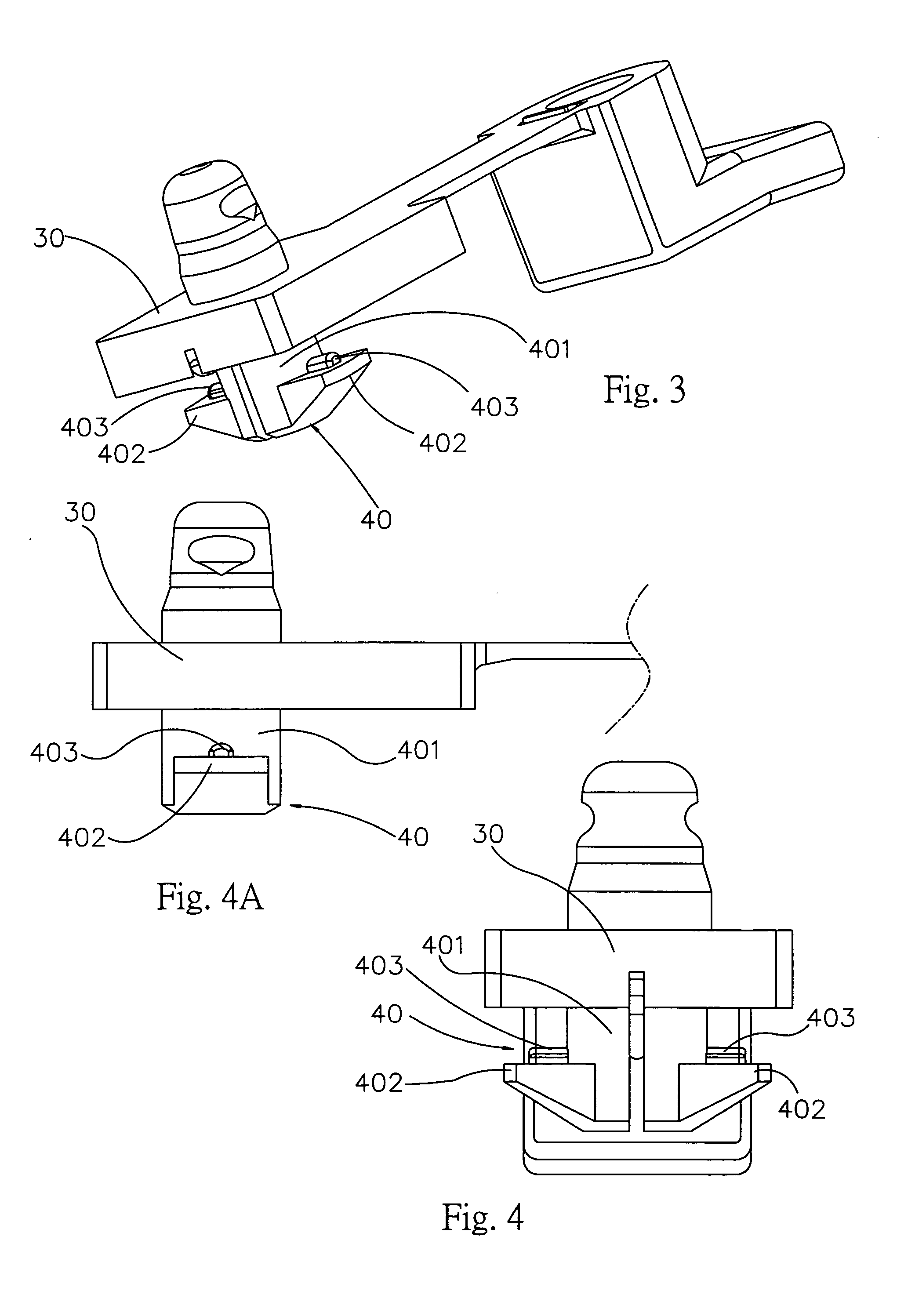
[0022]Referring to FIGS. 3, 4 and 4A, a mounting pin 40 is shown extending downwards from the bottom side of a frame body 30. The mounting pin 40 comprises a shank 401, two hooked portions 402 bilaterally extending from the bottom end (free end) of the shank 401, and two locating blocks 403 respectively protruded from the flat top side of each of the hooked portions 402. The hooked portions 402 have a width slightly smaller than the diameter of the shank 401.

[0023]Referring to FIG. 5, the mounting pin 40 is connectable to one plughole 51 of a circuit board 50 to secure the frame body 30 to the circuit board 50. The plughole 51 comprises a center hole 501, two border holes 502 disposed in communication with the center hole 501 at two opposite sides, and two retaining holes 503 disposed in communication with the center hole 501 at two opposite sides and equally spaced from the border holes 502. The border holes 502 have a diameter smaller than the center hole 501.

[0024]Referring to FI...


PUM


Abstract

A mounting pin and plughole arrangement is disclosed include a plughole formed on a circuit board, and a mounting pin downwardly extending from a frame body and having a shank with two hooked portions for fastening to the plughole to lock the frame body to the circuit board by: inserting the shank of the mounting pin through the center of the plughole and then rotating the mounting pin through an angle to force top locating blocks of the hooked portions into engagement with retaining holes that form a part of the plughole.

Description

[0001]This application claims the priority benefit of Taiwan patent application serial No. 96108996 filed on Mar. 15, 2007.BACKGROUND OF THE INVENTION[0002]1. Field of the Invention[0003]The present invention relates to a mounting pin and plughole arrangement for the connection of a frame body of a device to a circuit board. More specifically, the present invention relates to a mounting pin and plughole arrangement, which allows the mounting pin to be locked to the plughole through a rotary motion.[0004]2. Description of the Related Art[0005]Following fast development of technology, different advanced electronic devices have been continuously developed to bring convenience to people. To satisfy market demand, advanced electronic products are made to have a small size, which is convenient for carriage and storage. Therefore, computer and electronic products manufacturers put a lot of efforts to develop electronic products with light, thin, short and small characteristics.[0006]Many i...

Claims


Application Information

Patent Timeline
IPC IPC(8): H01R13/62
CPCH05K7/1417H05K7/12
Inventor HSU, RONG-XIAN
Owner T CONN PRECISION CORP
Why Eureka
Try Eureka