Holding Rod

a technology of holding rods and rods, which is applied in the direction of discharge tubes/lamp details, incadescent body mountings/supports, electric discharge lamps, etc., can solve the problems of only limited geometric enlargement, radioactive thorium used for this purpose, and breakag

Inactive Publication Date: 2011-03-17
OSRAM GMBH
View PDF1 Cites 2 Cited by
  • Summary
  • Abstract
  • Description
  • Claims
  • Application Information

AI Technical Summary

Problems solved by technology

One disadvantage of this material composition is the fact that it is very brittle and thus, in the case of high-wattage discharge lamps, i.e. in particular in the case of lamps with a wattage greater than 2 kW, breakages occur again and again during transportation since such discharge lamps have very heavy anodes and long holding rod lengths.
Owing to the compact ...

Method used


Image

  • Holding Rod
  • Holding Rod
  • Holding Rod

Examples


Embodiment Construction

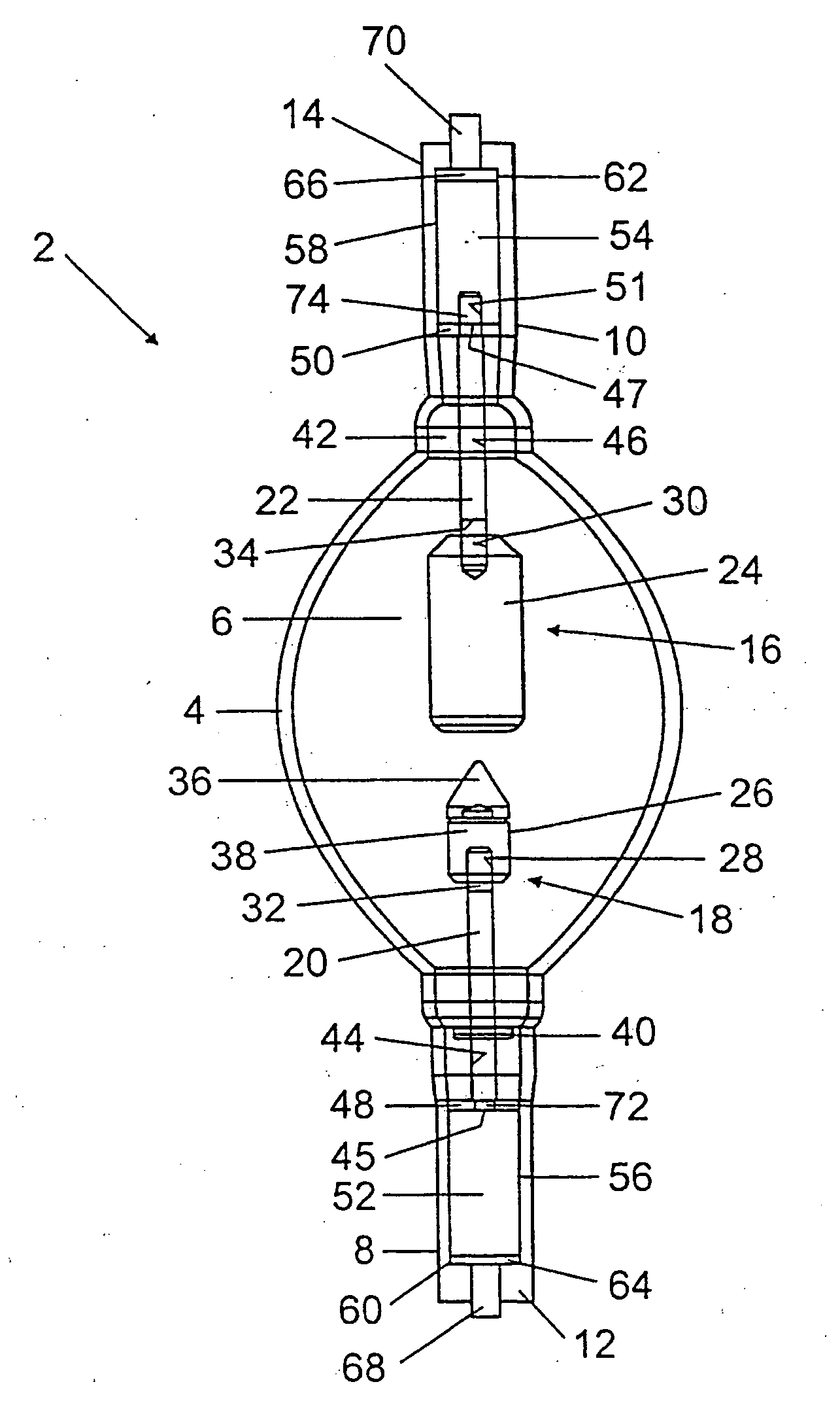
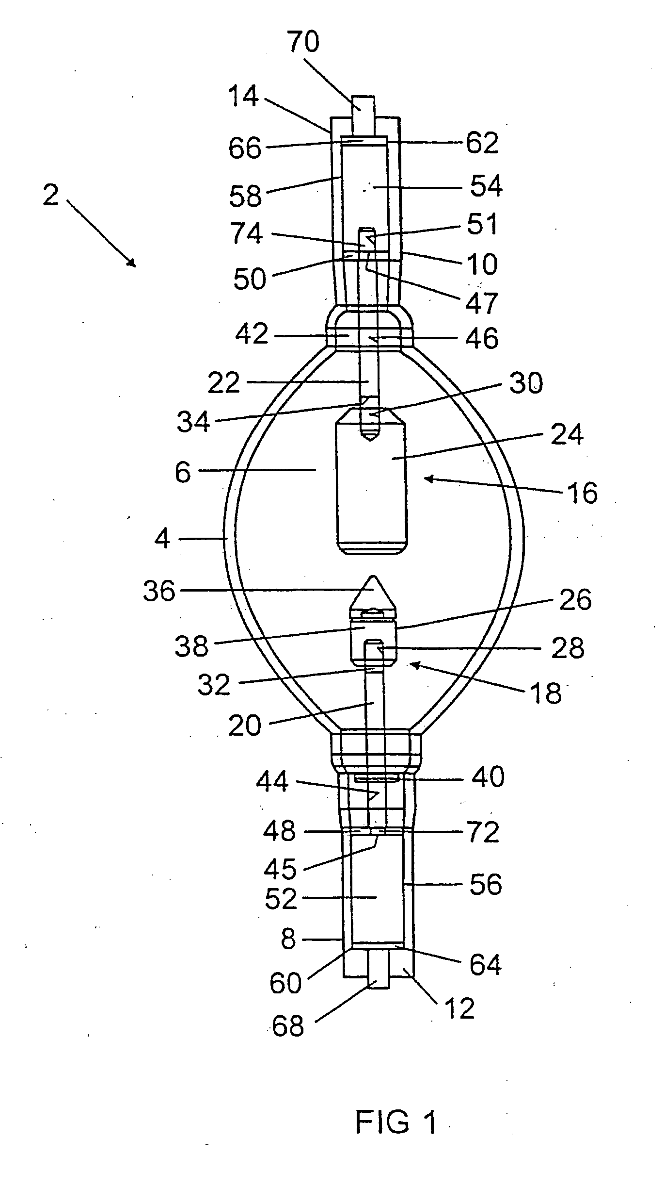
[0005]The invention is based on the object of providing a holding rod for holding an anode or cathode of a discharge lamp, which has a high strength in order to avoid breakages and whose material composition does not represent a radioactive load for the environment. The invention is likewise based on the object of providing a discharge lamp having at least one such holding rod.

[0006]This object is achieved as regards the holding rod by the features of patent claims 1 and 5 and as regards the discharge lamp by the features of patent claim 9. Particularly advantageous embodiments of the invention are described in the dependent claims.

[0007]The holding rod according to the invention for a discharge lamp, in particular a mercury vapor or xenon short-arc lamp, for holding an anode or cathode in an interior of a discharge vessel contains molybdenum doped according to the invention.

[0008]An alternative solution according to the invention is provided by a holding rod, in the case of which t...


PUM


Abstract

The invention discloses a holding rod 20, 22 for a discharge lamp 2, in particular a mercury vapor or xenon short-arc lamp, for holding an anode 24 or cathode 26 in an interior 6 of a discharge vessel 4, the holding rod 20, 22 containing doped molybdenum or tungsten doped with at least one metal oxide compound. Furthermore, the invention discloses a discharge lamp having such a holding rod 20, 22.

Description

TECHNICAL FIELD[0001]The invention relates to a holding rod for holding an anode or cathode in accordance with patent claims 1 and 5 and to a discharge lamp having at least one such holding rod.PRIOR ART[0002]Discharge lamps, in particular mercury vapor or xenon short-arc lamps, generally have two holding rods for holding their anode and cathode in a discharge chamber, said two holding rods consisting of tungsten doped with potassium. One disadvantage of this material composition is the fact that it is very brittle and thus, in the case of high-wattage discharge lamps, i.e. in particular in the case of lamps with a wattage greater than 2 kW, breakages occur again and again during transportation since such discharge lamps have very heavy anodes and long holding rod lengths. Mentioned by way of example is a conventional 5 kW mercury vapor short-art lamp which has an anode mass of approximately 1000 g and a holding rod length of approximately 100 mm.[0003]One possibility for avoiding s...

Claims


Application Information

Patent Timeline
IPC IPC(8): H01K1/18
CPCH01J61/0735H01J61/86H01J61/366H01J61/073
Inventor KOGER, RAINERSTEIN, KLAUS-DIETER
Owner OSRAM GMBH
Why Eureka
Try Eureka