Display device

a display device and interface terminal technology, applied in the field of display devices, can solve the problems of difficult connection of the interface terminals of the two flexible wiring boards to the connectors or probe pins of the inspection device, and achieve the effect of avoiding the failure of the inspection device to work properly

Active Publication Date: 2011-05-19
JAPAN DISPLAY INC +1
View PDF3 Cites 25 Cited by
  • Summary
  • Abstract
  • Description
  • Claims
  • Application Information

AI Technical Summary

Benefits of technology

[0007]The present invention aims to eliminate a shift of terminals electrically connected through separate flexible wiring boards.
[0008](1) A touch panel-attached display device including a display panel and a touch panel disposed so as to overlap with the display panel, wherein the display panel is connected to a first flexible wiring board on which a plurality of first wirings are arranged, the touch panel is connected to a second flexible wiring board on which a plurality of second wirings are arranged, the plurality of second wirings of the second flexible wiring board are connected to second connection terminals, the plurality of first wirings of the first flexible wiring board are connected to first connection terminals, and the first connection terminals and the second connection terminals are electrically connected to each other. According to this invention, the first and second flexible wiring boards can be easily electrically connected to each other.

Problems solved by technology

Therefore, it is difficult to connect the interface terminals of the two flexible wiring boards together to the connectors or probe pins of an inspection device.

Method used


Image

  • Display device
  • Display device
  • Display device

Examples


Embodiment Construction

[0018]Hereinafter, the embodiment of the present invention will be described with reference to the drawings. In the present embodiment, although a liquid crystal display device is described by way of an example of a display device, the present invention is not limited to this. The present invention can be applied to an organic electroluminescence display device, a plasma display device, a field emission display device, and the like.

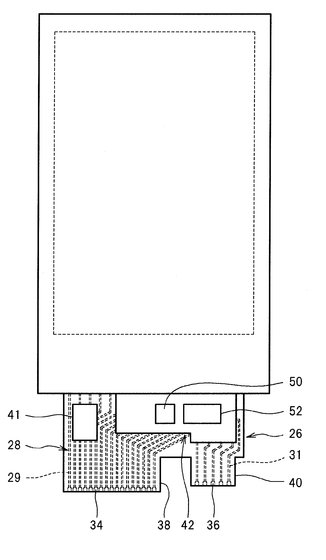
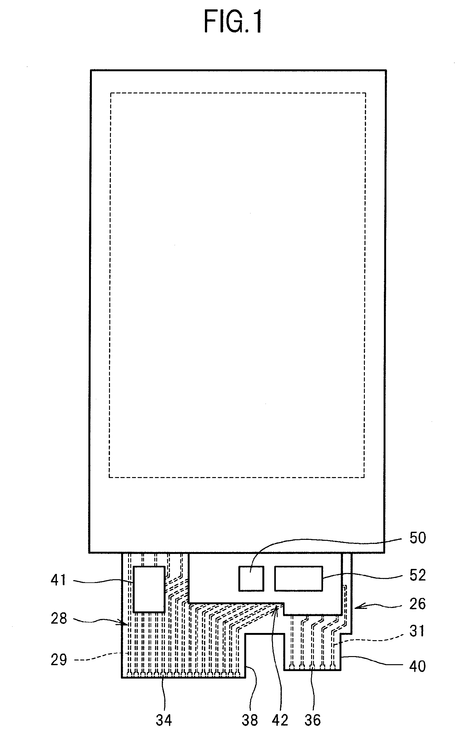
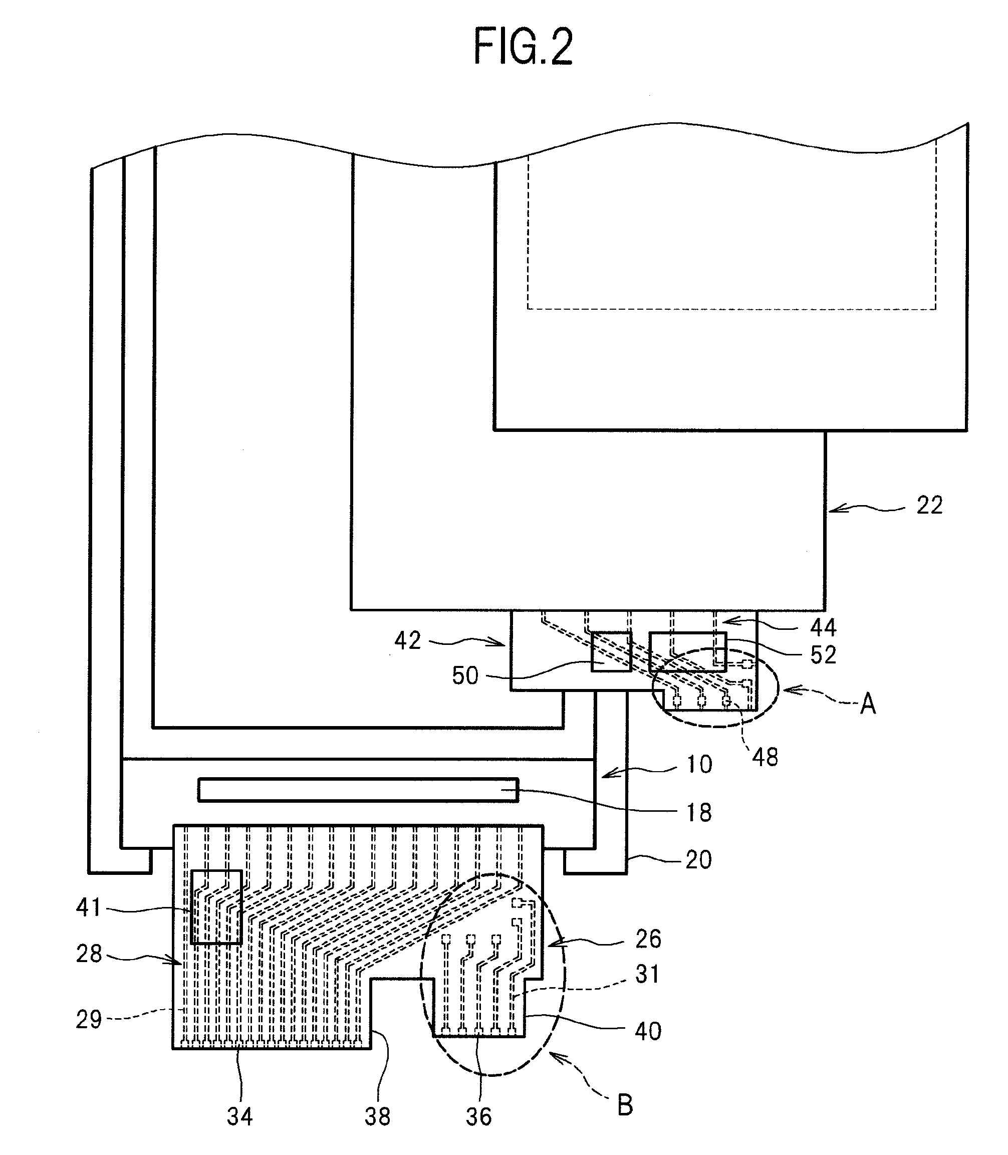
[0019]FIG. 1 is a top view showing a display device according to an embodiment of the present invention. FIG. 2 is an exploded top view of the display device shown in FIG. 1. FIG. 3 is an enlarged cross-sectional view of a part of the display device shown in FIG. 1.

[0020]As shown in FIG. 3, a display device includes a display panel 10. In the present embodiment, the display panel 10 is a liquid crystal display panel and includes a pair of substrates 12 and 14 (glass substrates) in which liquid crystals (not shown) are interposed between the two substrates...


PUM


Abstract

A display device includes a display panel and a touch panel disposed so as to overlap with the display panel. The display panel is connected to a first flexible wiring board on which a plurality of first wirings are arranged. The touch panel is connected to a second flexible wiring board on which a plurality of second wirings are arranged. The plurality of second wirings of the second flexible wiring board are connected to second connection terminals. The plurality of first wirings of the first flexible wiring board are connected to first connection terminals. The first connection terminals and the second connection terminals are electrically connected to each other.

Description

CROSS-REFERENCE TO RELATED APPLICATION[0001]The present application claims priority from Japanese application JP2009-261961 filed on Nov. 17, 2009, the content of which is hereby incorporated by reference into this application.BACKGROUND OF THE INVENTION[0002]1. Field of the Invention[0003]The present invention relates to a display device.[0004]2. Description of the Related Art[0005]Display devices having a structure in which a touch panel is superimposed on a display panel are known (see JP2008-83491A). A flexible wiring board is connected to the display panel, and a separate flexible wiring board is also connected to the touch panel. Interface terminals for connection to a circuit board are provided in each of the flexible wiring boards.[0006]In the related art, since separate flexible wiring boards are connected to the display panel and the touch panel, when there is a shift in the positions of the display panel and the touch panel, there is also a shift in the positions of the i...

Claims


Application Information

Patent Timeline
Patent Type & Authority Applications(United States)
IPC IPC(8): G06F3/041
CPCG06F2203/04103G06F3/041G06F3/04164
Inventor KUWAJIMA, YUKA
Owner JAPAN DISPLAY INC
Why Eureka
Try Eureka