
Bi-directional shift register and display device using same

Active Publication Date: 2006-12-19
SHARP KK
View PDF8 Cites 4 Cited by
  • Summary
  • Abstract
  • Description
  • Claims
  • Application Information

AI Technical Summary

Benefits of technology

[0029]The object of the present invention is to provide a driving circuit suitable for many purposes, capable of (A) switching shifting directions without needing conversion of external input signals inputted to the shift register circuit and (B) switching the shifting directions with a simple arrangement even if there are an even number of signal lines that are to be driven, and to provide a display device using the same.
[0032]When it is set, for example, that the number of output stages of the shift register circuit is an odd number, thus enabling to heighten the clock frequency without needing change to external input signals, and that an even number of signal lines are driven by the odd number of output signals, a displayed image is inevitably shifted by one pixel column between the rightward shifting and the leftward shifting, if relationship between the signal lines and output stages is fixed, as shown by the driving circuit in FIG. 9 as an example. However, by providing the signal line switching circuit section for switching over so as to change, between the rightward shifting and the leftward shifting, correspondence as to which signal line is driven by which output stage, thus shifting the image by one pixel column, it is possible to eliminate the shifting of pixels caused by the different shifting directions.
[0035]As described above, the driving circuit of the present invention is suitable for many purposes, capable of (A) switching shifting directions without needing change to external input signals inputted to the shift register circuit and (B) switching the shifting directions with a simple arrangement even if there are an even number of signal lines that are to be driven.
[0036]Therefore, the image display device of the present invention including such driving circuit in at least one of the data signal line driving circuit and the scanning signal line driving circuit is capable of ensuring flexibility in setting-up the display device, while keeping a simple arrangement of said at least one of the data signal line driving circuit and the scanning signal line driving circuit.

Problems solved by technology

However, the circuit arrangements in FIGS. 8 to 10 have the following problems.
This causes a problem in dealing with a high clock frequency.
This causes a problem that an image displaying position within an image module is shifted by one column.
This results in more electric power consumption if it is so arranged that current is supplied during the HIGH period.

Method used


Image

  • Bi-directional shift register and display device using same
  • Bi-directional shift register and display device using same
  • Bi-directional shift register and display device using same

Examples


Embodiment Construction

[0051]Referring to FIGS. 1 to 6, the following describes an embodiment of the present invention.

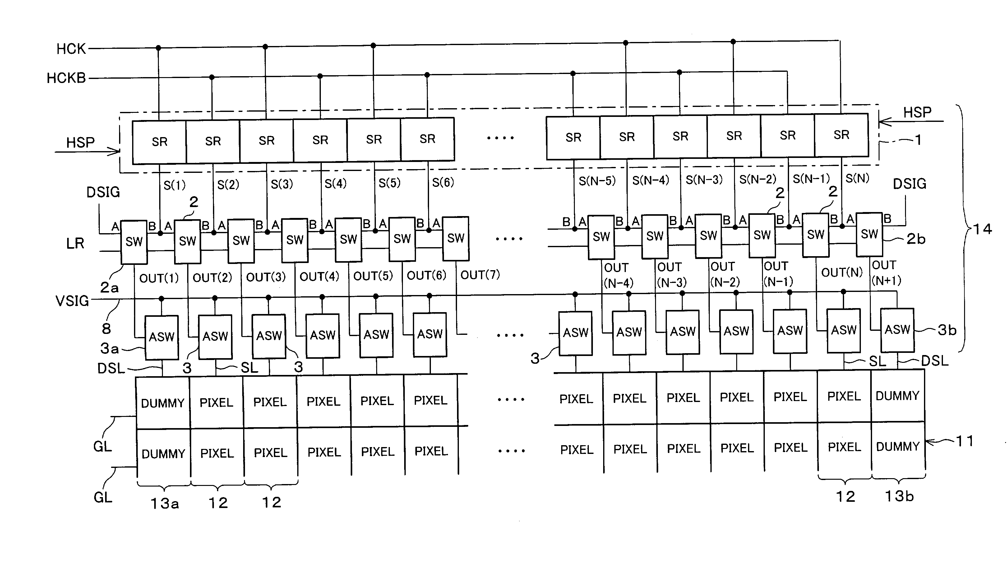
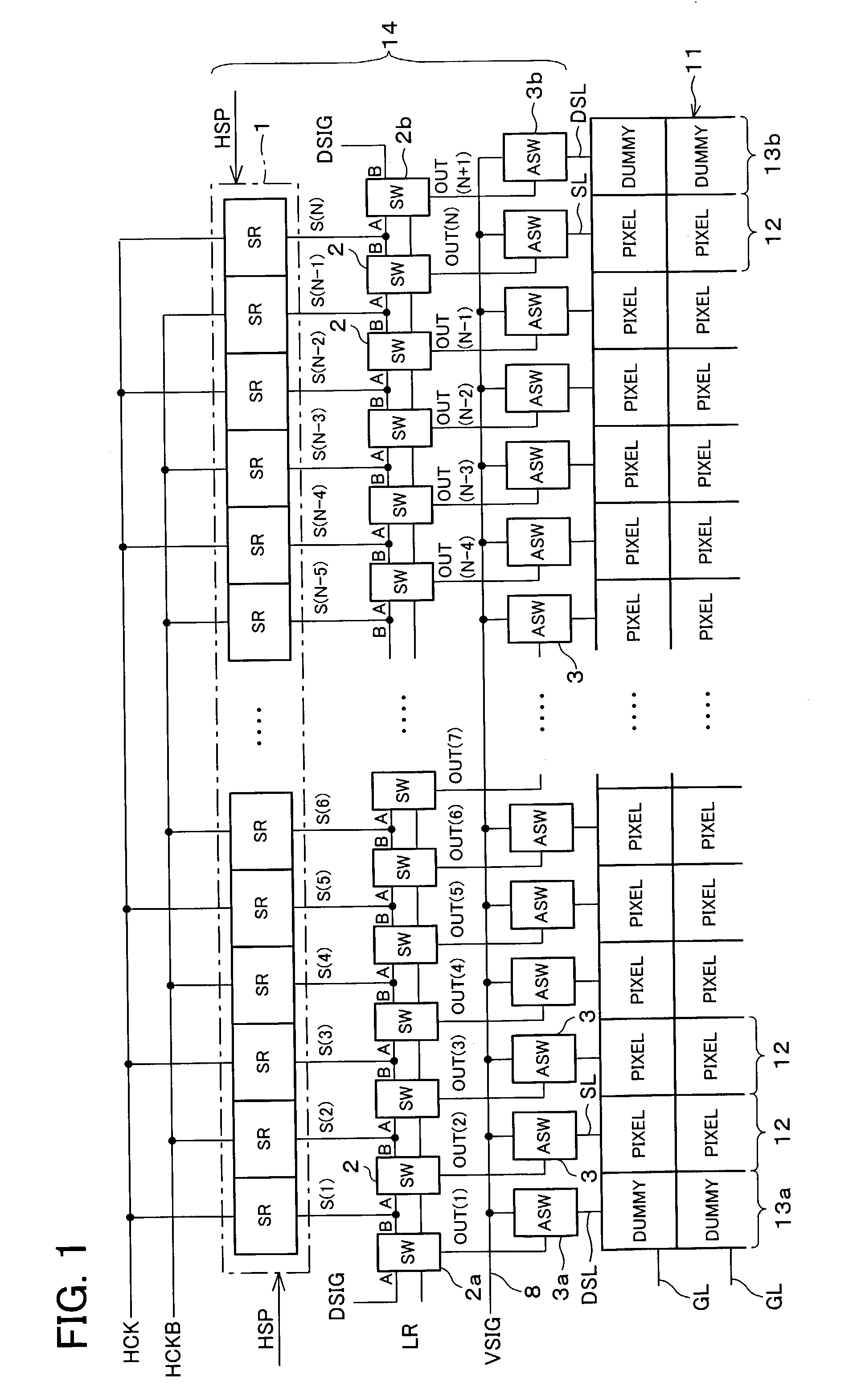
[0052]FIG. 1 is a block diagram illustrating a source driver 14 of a matrix-type image display device of the present embodiment to which an arrangement of a driving circuit of the present invention is applied. It is possible to use the source driver 14 as, for example, the source driver 34 of the liquid crystal display device, the basic arrangement of which is shown in FIG. 7.

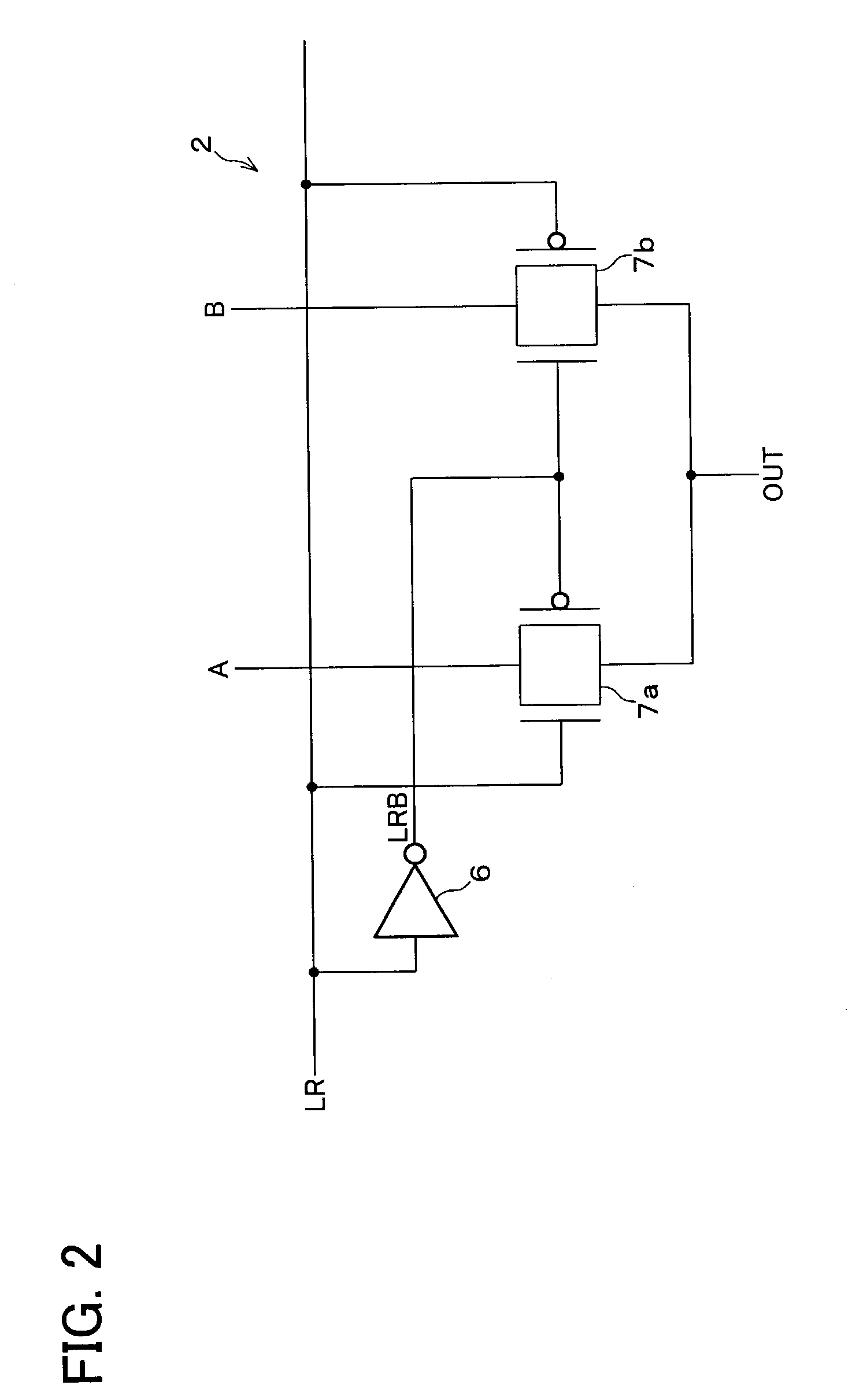
[0053]The source driver 14 includes a shift register circuit 1 that is capable of switching shifting directions between right and left, a plurality of sampling analog switches (analog switch circuits, ASW in FIG. 1) 3, which respectively turn ON and OFF in accordance with output signals supplied from output stages (SR in FIG. 1) of the shift register circuit 1. Further, as a characterizing arrangement of the present invention, the source driver 14 includes a plurality of switching circuits (SW in FIG. 1) 2, between o...


PUM


Abstract

A driving circuit of the present invention includes a signal line switching circuit section that connects each signal line with two adjacent ones of output stages of a shift register circuit, one of the two adjacent ones of output stages following the other, switches over so that the signal lines are, in the switching-over manner and in concert, driven either by the following output stages or by the followed output stages. Thus, it is possible to provide a driving circuit that can be freely placed in any manner, is suitable for many purposes, and is capable of switching shifting directions without needing inversion of a clock signal and without causing shift of pixels, and switching the shifting directions with a simple arrangement even if there are an even number of signal lines for driving effective pixel columns.

Description

FIELD OF THE INVENTION[0001]The present invention relates to a driving circuit including a shift register circuit for sequentially shifting, in accordance with a clock signal, data inputted thereto, and to a display device using the same. More specifically, the present invention relates to a driving circuit including a bi-directional shift register circuit that is capable of switching shifting directions, and to a display device using the same.BACKGROUND OF THE INVENTION[0002]Matrix-type image display devices (display devices) have come into practical use in office automation equipments and audiovisual equipments, and are used in moving picture display devices having large area and high fineness. Recently, such matrix-type image display devices have been developed as to have, on a single substrate, a display section having pixel arrays, and a peripheral driving circuit section. In such matrix-type image display devices, therefore, a driving circuit is integrated with the display sec...

Claims


Application Information

Patent Timeline
IPC IPC(8): G09G3/36G09G3/20G02F1/133G11C19/00
CPCG09G3/3688G11C19/00G09G2310/0283G09G3/36
Inventor OHKAWA, HIROYUKIOGAWA, YASUYUKISAKAI, TAMOTSUMAEDA, KAZUHIRO
Owner SHARP KK
Learn More