Integrated gate driver circuit and driving method therefor

a gate driver and integrated technology, applied in electronic switching, pulse technique, instruments, etc., can solve the problems of increasing the number of driver circuits, increasing the manufacturing cost, and limited space for forming gate driver circuits thereon, so as to reduce the manufacturing cost, and simplify the circuit structure

Active Publication Date: 2012-11-06
HANNSTAR DISPLAY CORPORATION
View PDF7 Cites 5 Cited by
  • Summary
  • Abstract
  • Description
  • Claims
  • Application Information

AI Technical Summary

Benefits of technology

[0009]The present invention provides an integrated gate driver circuit, wherein each driving unit only needs two switching devices such that it has simpler circuit structure and lower manufacturing cost and needs less circuit space.
[0010]The present invention further provides an integrated gate driver circuit, wherein the charging and discharging to the output voltage of each driving unit are performed through the same switching device so as to eliminate the shift of the critical voltage of switching devices.
[0011]The present invention further provides an integrated gate driver circuit, wherein each driving unit can operate in conjunction with a voltage stabilizing circuit so as to stabilize the output voltage of the integrated gate driver circuit.

Problems solved by technology

Therefore, the number of driver circuits is increased and the manufacturing cost is also increase at the same time.
However, because great numbers of gate lines, data lines and pixels have to be formed simultaneously on one substrate, limited space is available for forming the gate driver circuits thereon.
However, since each driving stage of the shift register still includes six thin film transistors, the shift register has complicated structure and needs larger manufacturing space.

Method used


Image

  • Integrated gate driver circuit and driving method therefor
  • Integrated gate driver circuit and driving method therefor
  • Integrated gate driver circuit and driving method therefor

Examples


Embodiment Construction

[0031]It should be noticed that, wherever possible, the same reference numbers will be used throughout the drawings to refer to the same or like parts.

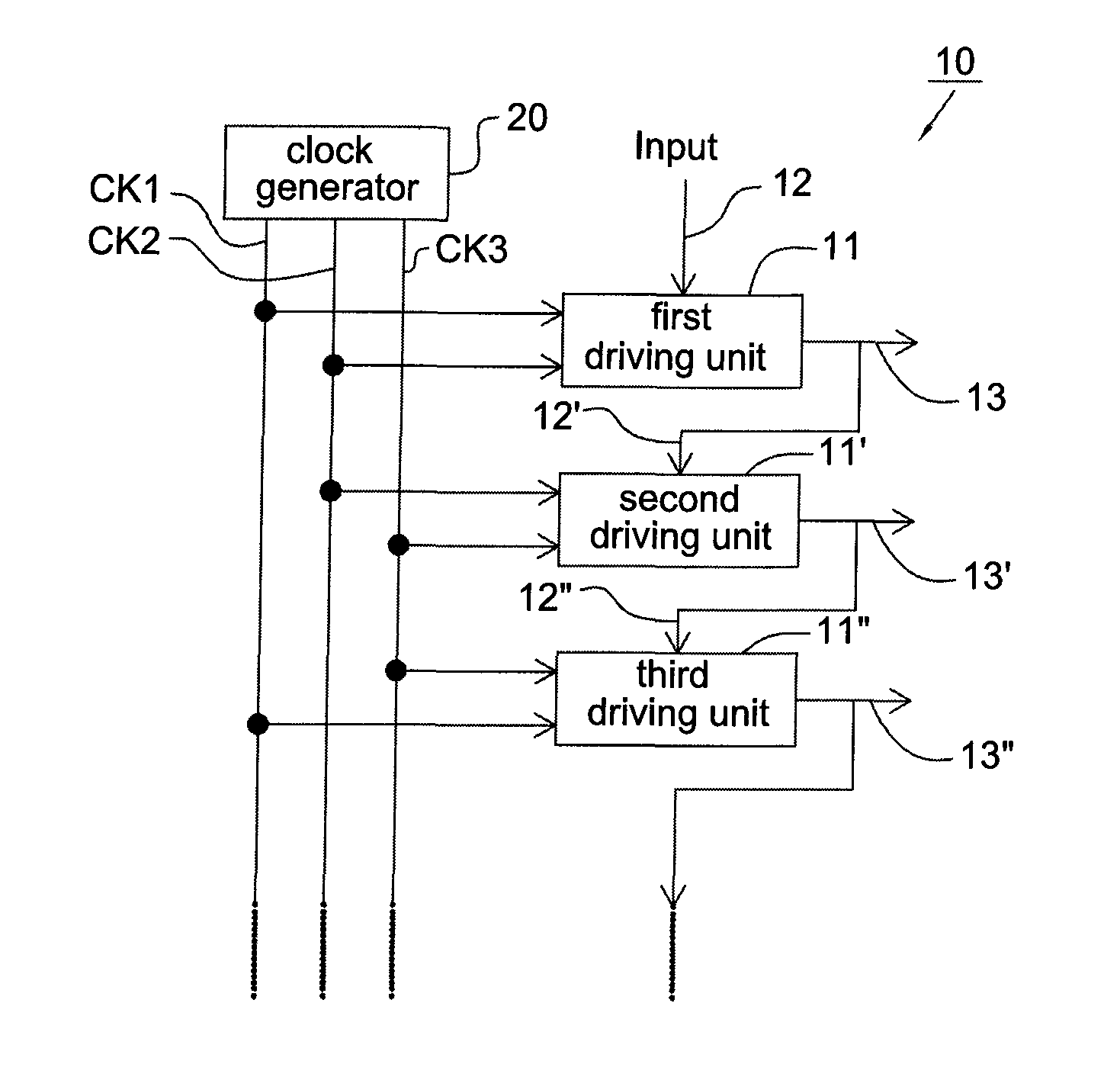
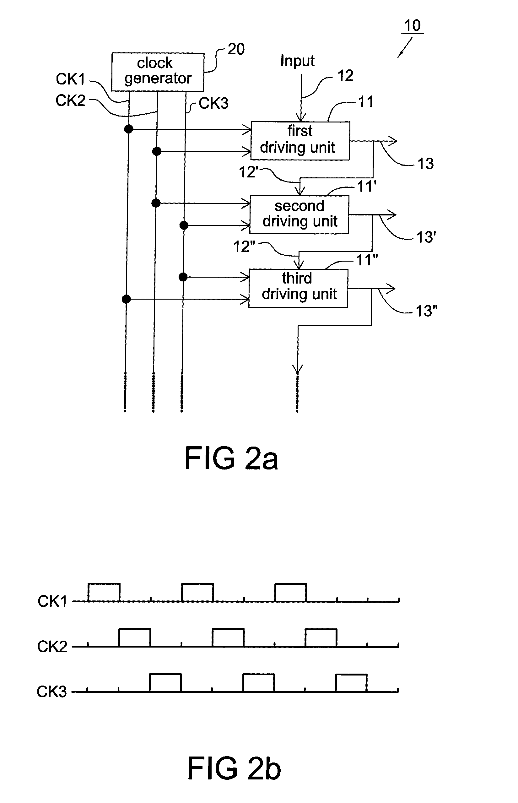
[0032]Please refer to FIG. 2a, it shows a block diagram of the integrated gate driver circuit 10 according to an embodiment of the present invention. The integrated gate driver circuit 10 includes a plurality of driving units cascaded in series, e.g. a first driving unit 11 (served as the first stage of all driving units), a second driving unit 11′ and a third driving unit 11″ as shown in the figure, and receives an input signal and a plurality of clocks, wherein the clocks are provided by a clock generator 20, which may be included or not included in the integrated gate driver circuit 10.

[0033]Each driving unit, e.g. the first driving unit 11 includes a signal input terminal 12 and an output terminal 13, and receives two clocks CK1 and CK2. The output terminal of each driving unit is coupled to the signal input terminal of the immedi...


PUM


Abstract

An integrated gate driver circuit receives a plurality of clocks and includes a plurality of driving units cascaded in series. Each driving unit is for driving a load and includes an input terminal, an output terminal, a first switch and a second switch. The first switch has a first terminal coupled to the input terminal, a second terminal coupled to a first node, and a control terminal receiving a first clock, and the first switch is turned on when the first clock is at high level. The second switch has a first terminal receiving a second clock, a second terminal coupled to the output terminal, and a control terminal coupled to the first node, wherein the second clock charges and discharges the load through the second switch when the first node is at high level; wherein the output terminal of each driving unit is coupled to the input terminal of the immediately succeeding driving unit.

Description

CROSS REFERENCE TO RELATED APPLICATION[0001]This application claims the priority benefit of Taiwan Patent Application Serial Number 097135947, filed on Sep. 19, 2008, the full disclosure of which is incorporated herein by reference.BACKGROUND[0002]1. Field of the Invention[0003]This invention generally relates to a gate driver circuit and, more particularly, to an integrated gate driver circuit for a liquid crystal display.[0004]2. Description of the Related Art[0005]A liquid crystal display 9 generally includes a pixel matrix 91, a plurality of gate driver circuits 92 and a plurality of source driver circuits 93, as shown in FIG. 1a. The pixel matrix 91 includes a plurality of gate lines, a plurality of data lines and pixels (not shown) located at the crossovers of the gate lines and the data lines. Each gate driver circuit 92 is coupled to a row of pixels through a gate line for sequentially providing a scanning signal to the pixel matrix 91. The source driver circuit 93 is couple...

Claims


Application Information

Patent Timeline
Patent Type & Authority Patents(United States)
IPC IPC(8): G09G3/36
CPCG09G3/3677
Inventor CHEN, YAN JOULU, YUNG HSINYU, CHIA HUALIN, SUNG CHUN
Owner HANNSTAR DISPLAY CORPORATION
Why Eureka
Try Eureka