Brake apparatus, brake control unit, and brake control method

Active Publication Date: 2011-11-24
TOYOTA JIDOSHA KK
View PDF7 Cites 23 Cited by
  • Summary
  • Abstract
  • Description
  • Claims
  • Application Information

AI Technical Summary

Benefits of technology

[0030]The definitions of the “dead-band region”, the “residual pressure reduction condition”, and the “predetermined period” are as described above. Application of the brake control method according to the sixth aspect of the invention to the brake apparatus makes it possible to promptly bring the actual hydraulic pressure to the target hydraulic pressure. When the target hydraulic pressure is zero, it is possible to bring the actual hydraulic pr

Problems solved by technology

In the regular hydraulic control, it is difficult to decrease the actual hydraulic press

Method used


Image

  • Brake apparatus, brake control unit, and brake control method
  • Brake apparatus, brake control unit, and brake control method
  • Brake apparatus, brake control unit, and brake control method

Examples


first embodiment

of the Invention

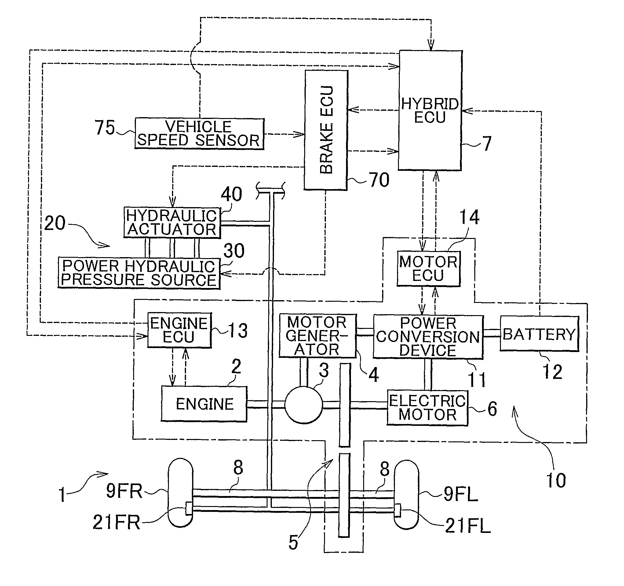
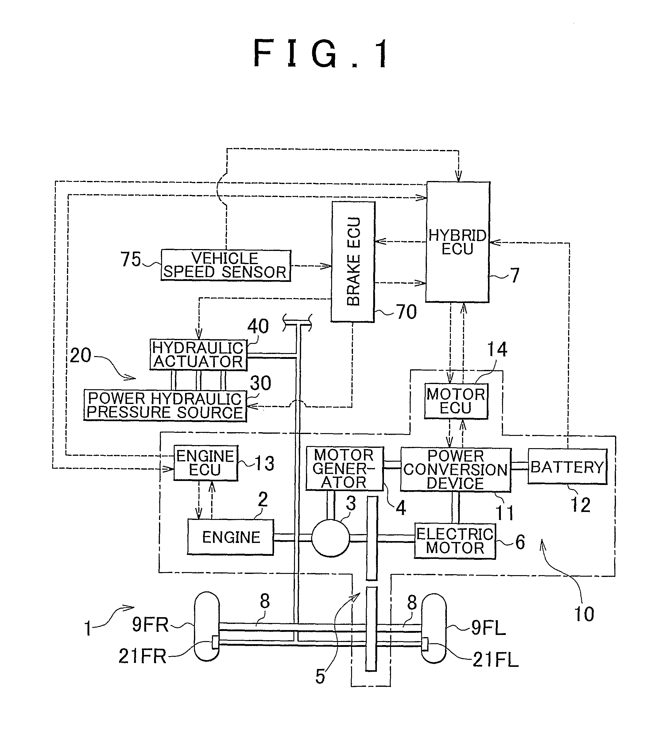
[0044]FIG. 1 is a view schematically showing a vehicle 1 provided with a brake apparatus according to a first embodiment of the invention. The vehicle 1 is a so-called hybrid vehicle. The vehicle 1 includes an engine 2, a three-axis power split mechanism 3 that is connected to a crankshaft which serves as an output shaft of the engine 2, a motor generator 4 that is connected to the power split mechanism 3 and that is able to generate electric power, an electric motor 6 that is connected to the power split mechanism 3 via a transmission 5, and electronic control units (hereinafter, referred to as “ECUs”) that control respective actuator. That is, as control units for the vehicle 1, there are provided a hybrid ECU 7 that controls the entirety of a drive system, an engine ECU 13 that controls the engine 2, a motor ECU 14 that controls each motor, and a brake ECU 70 that controls a brake. Each ECU is formed of a microprocessor that includes a CPU. Each ECU includes, in a...

second embodiment

of the Invention

[0102]Next, a second embodiment of the invention will be described. The second embodiment is mostly the same as the first embodiment except that the residual pressure reduction control is executed in controls other than the cooperative braking control. Therefore, the same reference numerals will be assigned to the components that are substantially the same as those in the first embodiment of the invention, and descriptions concerning these components will not be provided below.

[0103]FIG. 7 is a graph showing a main portion of a brake control method according to the second embodiment of the invention. FIG. 7 shows the state when the hydraulic pressure is decreased in the hydraulic braking control. FIG. 7 shows the target hydraulic pressure (indicated by a dashed line) and the actual hydraulic pressure (indicated by a solid line) of the hydraulic fluid in the hydraulic braking control. The region between the chain double-dashed lines is the dead-band region. The abscis...


PUM


Abstract

There is provide a brake control technology according to which a target hydraulic pressure is reliably achieved when a hydraulic pressure is decreased during hydraulic control and brake drag does not occur even when the target hydraulic pressure is zero. In a brake apparatus, a dead-band region is set for the target hydraulic pressure that is used in the hydraulic control. When braking control is switched from the hydraulic control to regenerative control in cooperative braking control, residual pressure reduction control is executed. In the residual pressure reduction control, the target hydraulic pressure is set to a value that is lower than zero to which the hydraulic pressure should be brought.

Description

INCORPORATION BY REFERENCE[0001]The disclosure of Japanese Patent Application No. 2007-210509 filed on Aug. 10, 2007 including the specification, drawings and abstract is incorporated herein by reference in its entirety.BACKGROUND OF THE INVENTION[0002]1. Field of the Invention[0003]The invention relates to brake control for controlling braking forces that are applied to wheels of a vehicle.[0004]2. Description of the Related Art[0005]For example, Japanese Patent Application Publication No. 2006-123889 (JP-A-2006-123889) describes a brake apparatus that achieves a target braking torque, which is determined based on an operation state and a traveling state of a vehicle, by performing regenerative braking control and hydraulic braking control in combination. Cooperative braking control is executed so that a total braking torque, which is a total sum of a regenerative braking torque and a hydraulic braking torque, matches a required braking torque that is a torque required by a driver....

Claims


Application Information

Patent Timeline
IPC IPC(8): B60T13/74G06F19/00B60K6/445B60T8/17B60W10/18B60W20/00
CPCB60K6/445B60T1/10B60T8/4081Y02T10/6239B60W10/08B60W10/184B60W20/00B60T2270/604Y02T10/62B60W10/188B60W30/18109
Inventor NAKATA, DAISUKEOKANO, TAKAHIROFUKASAWA, TSUKASA
Owner TOYOTA JIDOSHA KK
Why Eureka
Try Eureka