Pivoting display device

a display device and display device technology, applied in the direction of casings/cabinets/drawers, casings/cabinets/drawers, instruments, etc., can solve the problems of less reliability, complicated configuration of gear dampers, and wear of cords, so as to reduce the braking of the pivoting of the display unit and enhance reliability.

Inactive Publication Date: 2012-01-05
PANASONIC CORP
View PDF3 Cites 8 Cited by
  • Summary
  • Abstract
  • Description
  • Claims
  • Application Information

AI Technical Summary

Benefits of technology

[0024]As described above, according to the present invention, energy for stowage is accumulated in an elastic component when a display unit is drawn out to a display position, and the display unit can be automatically stowed into a stowing portion after used or when passage of electric current to a cabin is interrupted. Further, even when an urging force

Problems solved by technology

Therefore, the gear damper has a complicated configuration, and less reliability.
However, when braking utilizing a friction between the brake drum and the cord is repeated over a long time period, the cord is w

Method used


Image

  • Pivoting display device
  • Pivoting display device
  • Pivoting display device

Examples


first embodiment

[0039](First embodiment)

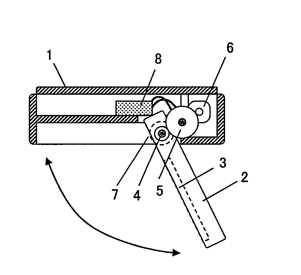
[0040]FIG. 1 shows a configuration of a counter-electromotive force control unit of a pivoting display device according to a first embodiment of the present invention, which is stowed in stowing portion provided in a ceiling area of a passenger airplane, especially in a stowing portion below a baggage rack / compartments. FIG. 2 and FIG. 3 show a schematic configuration thereof.

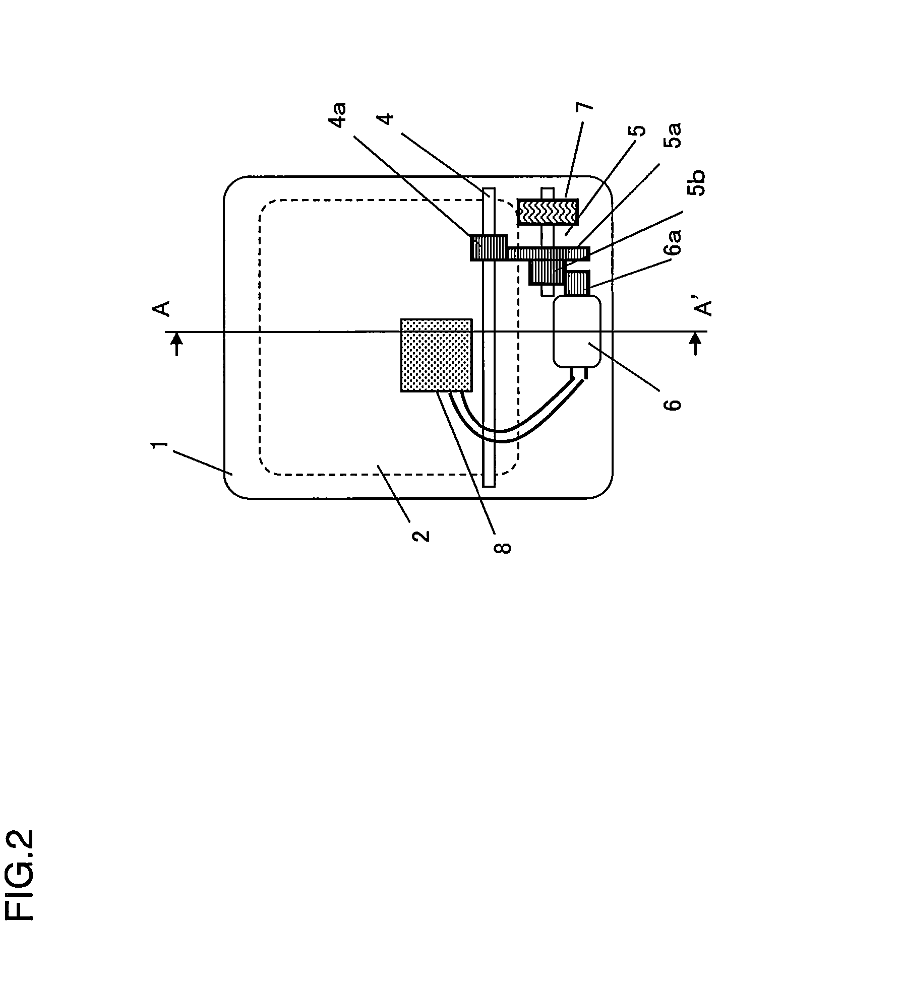
[0041]FIG. 2 is a top view of the pivoting display device, and FIG. 3 is a cross-sectional view taken along a line A-A′ of FIG. 2. FIG. 3(a) shows a display unit in a stowed state, and FIG. 3(b) shows the display unit in a used state.

[0042]As shown in the drawings, a monitor 2 acting as the display unit is mounted below a body frame 1 of the pivoting display device, and is mounted, as a whole, in the stowing portion in a not-illustrated ceiling area of the passenger airplane, especially in the stowing portion below the baggage rack / compartments.

[0043]The monitor 2 is shaped like a rectan...

second embodiment

[0059](Second embodiment)

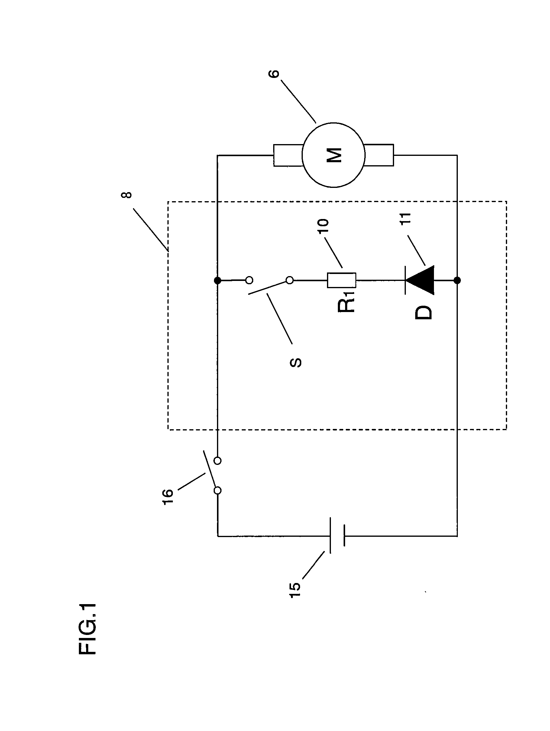
[0060]FIG. 8 is a block diagram illustrating a configuration of a counter-electromotive force control unit of a pivoting display device according to a second embodiment of the present invention. In FIG. 8, the same components as described in the first embodiment are denoted by the same reference numerals as shown in the block diagram of FIG. 4 illustrating the configuration of the counter-electromotive force control unit.

[0061]In FIG. 8, reference numeral 6 denotes a motor acting as a DC electromotor in a drive section, reference numeral 10 denotes a resistance for regulating electric current of a counter-electromotive force generated in the motor 6, reference numeral 11 denotes a diode acting as a rectifier for regulating flowing of electric current to the counter-electromotive force control unit when the motor 6 rotates forward, reference numeral 16 denotes a power switch of the pivoting display device, and reference numeral 15 denotes a power supply of th...

third embodiment

[0076](Third embodiment)

[0077]FIG. 12 is a block diagram illustrating a configuration of a pivoting display device according to a third embodiment of the present invention. In FIG. 12, the same components as described in the first embodiment are denoted by the same reference numerals as those of the configuration shown in the block diagram of FIG. 4.

[0078]The configuration shown in FIG. 12 is different from the configuration shown in FIG. 4 for the first embodiment in that a plurality of circuits each formed by the FET 12 and the resistances 10, 13, and 14 in the counter-electromotive force control unit 8 are connected in parallel with the motor 6, and the FETs 12 and the resistances 10, 13, and 14 included in the plurality of circuits are represented by FETs 121 to 12N, resistances 101 to 10N, 131 to 13N, and 141 to 14N, respectively.

[0079]Values of the resistances 101 to 10N, 131 to 13N, and 141 to 14N connected to the FETs 121 to 12N, respectively, are individually determined, to...


PUM


Abstract

An object of the present invention is to make available a pivoting display device which enables a display unit to be assuredly stowed even by using a relatively small elastic component, and which has enhanced reliability and is space-saving. When a power switch becomes off, a monitor which can be stowed is swung by urging force from a coil spring. In an initial stage in which counter-electromotive force Vm induced by a motor is greater than on-voltage of a FET, the counter-electromotive force Vm acts as rotation resistance for the motor. When the monitor approaches a stowage position, the rotating speed of the motor is reduced. Therefore, bias voltage of the FET is reduced due to reduction of the counter-electromotive force Vm, and the braking force imposed on the motor by the counter-electromotive force Vm is gradually reduced, thereby increasing pivoting speed.

Description

CROSS REFERENCE TO RELATED APPLICATION[0001]The disclosure of Japanese Patent Application No.2010-151781, filed on July 2, 2010, is incorporated herein by reference.BACKGROUND OF THE INVENTION[0002]1. Field of the Invention[0003]The present invention relates to pivoting display devices that are mounted to the ceiling area of cabins of, for example, passenger airplanes, and that swing display units open from a stowage position to a display position when used.[0004]2. Description of the Background Art[0005]In recent years, display devices are often mounted in transportation means such as airplanes, trains, busses, and passenger boats to provide passengers with video image content and information.[0006]Passengers increasingly desire to individually enjoy various video images in transportation means, and it is desired to provide pivoting display devices having thin lightweight display units which can be mounted in minimized space.[0007]Therefore, especially in passenger airplanes, pivot...

Claims


Application Information

Patent Timeline
IPC IPC(8): H05K5/02
CPCH05K5/02
Inventor TANAKA, YUSUKETSUDA, HIROSHI
Owner PANASONIC CORP
Why Eureka
Try Eureka