Method of logging measurement result at handover failure in wireless communication system

Active Publication Date: 2012-03-15
LG ELECTRONICS INC
View PDF11 Cites 74 Cited by
  • Summary
  • Abstract
  • Description
  • Claims
  • Application Information

AI Technical Summary

Benefits of technology

[0015]Therefore, an object of the present invention is to effectively establish network's set up using

Problems solved by technology

However, the network does not know when, how and where

Method used


Image

  • Method of logging measurement result at handover failure in wireless communication system
  • Method of logging measurement result at handover failure in wireless communication system
  • Method of logging measurement result at handover failure in wireless communication system

Examples


Example

[0033]One aspect of this disclosure relates to the recognition by the present inventors about the problems of the related art as described above, and further explained hereafter. Based upon this recognition, the features of this disclosure have been developed.

[0034]Although this disclosure is shown to be implemented in a mobile communication system, such as a UMTS developed under 3GPP specifications, this disclosure may also be applied to other communication systems operating in conformity with different standards and specifications.

[0035]Hereinafter, description of structures and operations of the preferred embodiments according to the present invention will be given with reference to the accompanying drawings.

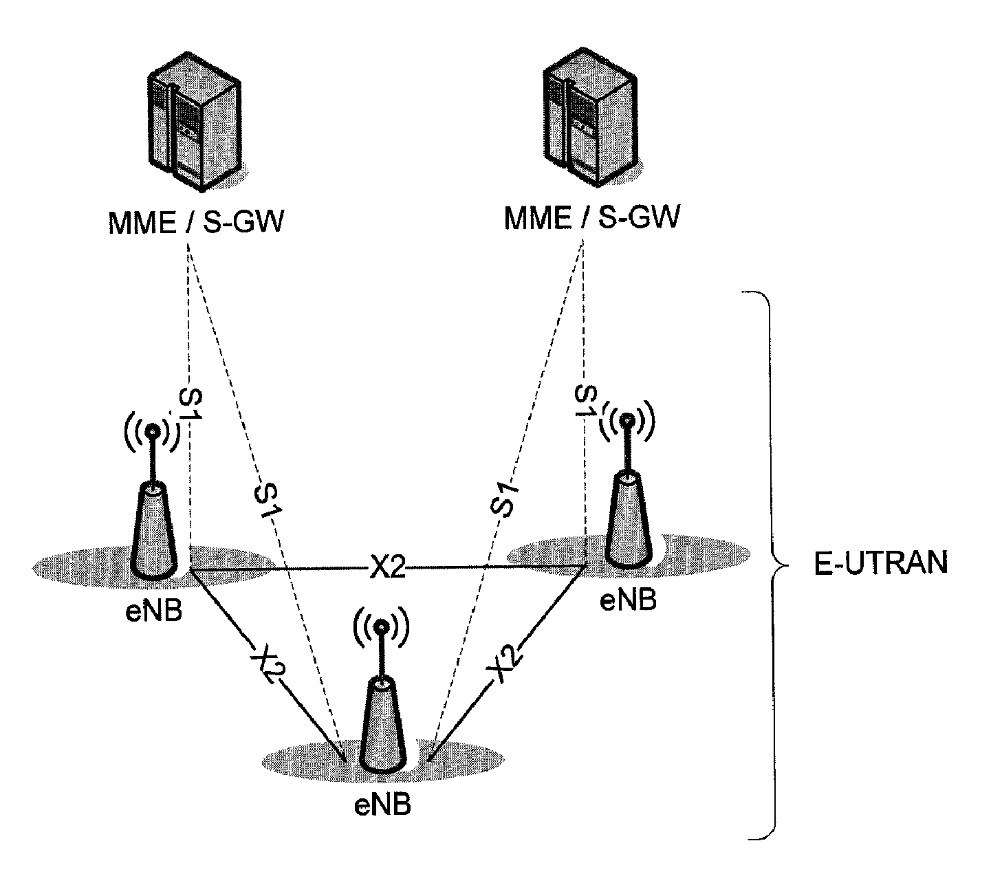
[0036]Firstly, a description of measurement will be given as following. In a mobile communication system, it is essentially required to support the mobility of the UE. To support the mobility, the UE continues to measure the quality of a serving cell currently providing a ser...


PUM


Abstract

Disclosed is related to a wireless communication system and a mobile terminal providing a wireless communication service and to a method by which a base station and a mobile terminal transmit and receive data in an evolved universal mobile telecommunications system (E-UMTS) evolved from universal mobile telecommunications system (UMTS), a long term evolution (LTE) system, or a LTE-advanced (LTE-A) system and more particularly, to a method of logging a measurement result at a handover failure.

Description

TECHNICAL FIELD [0001]The present invention relates to a wireless communication system and a mobile terminal providing a wireless communication service and to a method by which a base station and a mobile terminal transmit and receive data in an evolved universal mobile telecommunications system (E-UMTS) evolved from universal mobile telecommunications system (UMTS), a long term evolution (LTE) system, or a LTE-advanced (LTE-A) system and more particularly, to a method of logging a measurement result at a time of handover failure.BACKGROUND ART [0002]FIG. 1 is a view illustrating a network architecture of an Evolved Universal Terrestrial Radio Access Network (E-UTRAN), which is a mobile communication system to which the related art and the present invention are applied. The E-UTRAN system has evolved from the existing UTRAN system, and a basic standardization work thereof is currently going on in 3GPP. The E-UMTS system may be also referred to as a Long Term Evolution (LTE) system.[...

Claims


Application Information

Patent Timeline
IPC IPC(8): H04W24/00
CPCH04W16/18H04W24/04H04W36/0094H04W24/08
Inventor KIM, SUNHEEJUNG, SUNGHOONYI, SEUNGJUNECHUN, SUNGDUCKPARK, SUNGJUN
Owner LG ELECTRONICS INC
Why Eureka
Try Eureka