

Hinge apparatus for connecting first and second wind turbine blade components comprising a rotary actuator
- Summary
- Abstract
- Description
- Claims
- Application Information
AI Technical Summary
Benefits of technology
Problems solved by technology
Method used
Image

Examples
Embodiment Construction
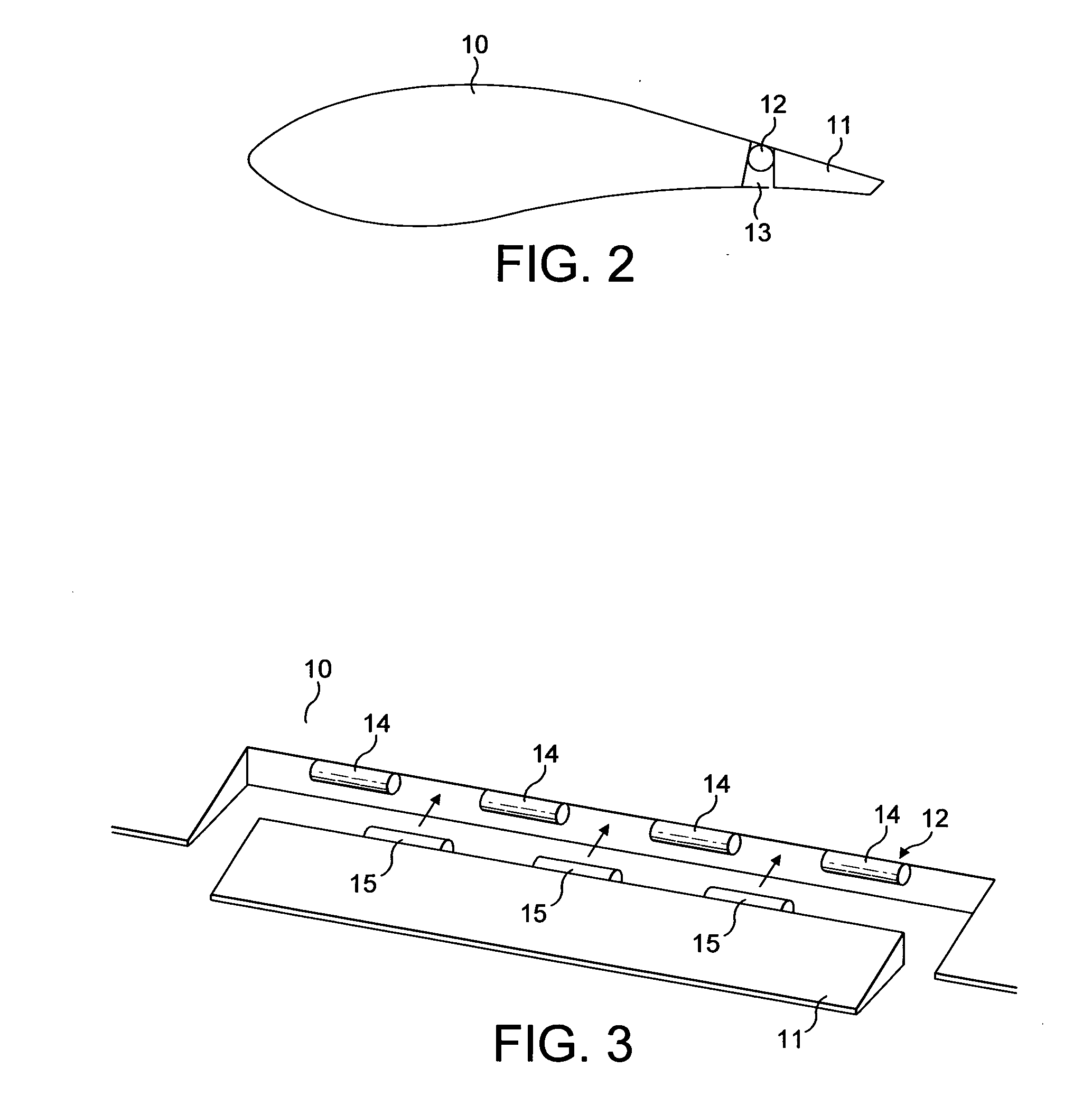
[0038]A first example of the invention will now be described with reference to FIGS. 2 and 3.
[0039]FIG. 2 is a lateral cross-section through the blade, showing both a blade 10 and a control surface 11, otherwise known as a flap or aileron. The control surface 11 is joined to the blade 10 by a hinge mechanism 12 having hinge cylinders or knuckles, and hinge pins. The axis about which the hinge rotates is positioned just below the surface of the blade, so that the surface of the hinge cylinder is flush with the blade surface thereby avoiding disruption of the air flow across the surface of the blade. Alternatively, the hinge cylinder could also be located so that it is entirely under the blade surface, providing this still allows control of the aileron in the manner desired.
[0040]The top surface of the blade 10 is configured to contiguously join the hinge cylinder, or to cover it depending on the implementation. On the leeward side of the blade, a lip 13 extends from the blade 10 to p...
PUM
 Abstract
Description
Claims
Application Information