Optical system for thermal image microscope

an optical system and thermal image technology, applied in the field of optical systems, can solve the problems of miniaturization of optical systems, excessive number of lenses used, and limited shape of lenses, so as to improve measurement accuracy

Inactive Publication Date: 2012-03-29
KOREA BASIC SCI INST
View PDF2 Cites 8 Cited by
  • Summary
  • Abstract
  • Description
  • Claims
  • Application Information

AI Technical Summary

Benefits of technology

[0006]The present invention provides an optical system for a thermal image microscope, in which measurement accuracy is improved through analysis of an optical path and aberration of the optical system.

Problems solved by technology

However, with the recent development of technology, functional lenses for removing or correcting aberration generated by a lens itself have been developed, and these lenses are appropriately combined to each other to form a complex lens optical system.
However, an excessive number of lenses are being used in a typical optical system for a thermal sensing apparatus, and the shape of the lens is mainly limited to a spherical optical system.
Accordingly, there are many limiting factors in miniaturization of an optical system, and image quality improvement and camera brightness for improving the function of the optical system.

Method used


Image

  • Optical system for thermal image microscope
  • Optical system for thermal image microscope
  • Optical system for thermal image microscope

Examples


Embodiment Construction

[0020]Hereinafter, exemplary embodiments of the present invention will be described in detail with reference to the accompanying drawings.

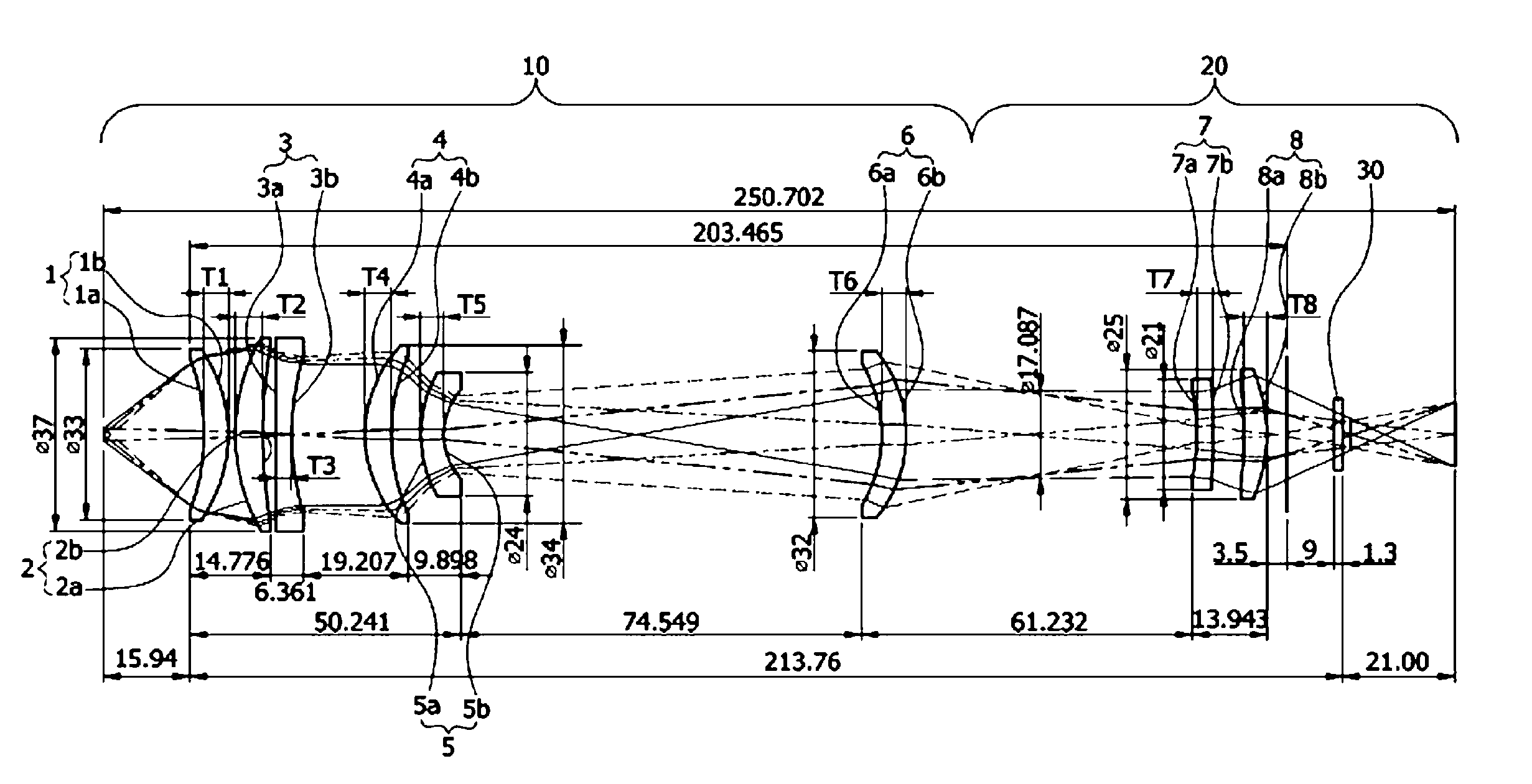
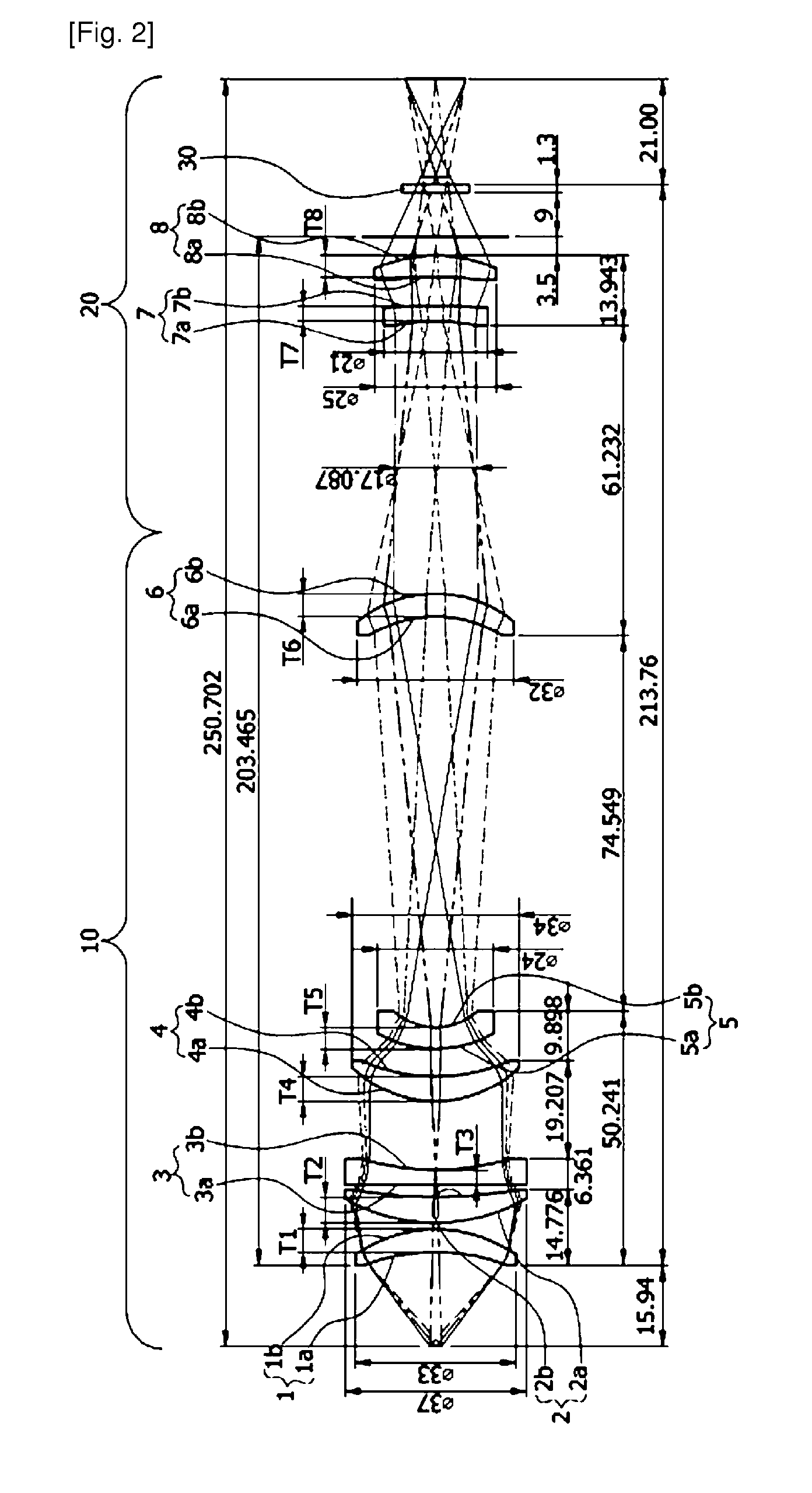
[0021]An optical system for a thermal image microscope may include a spherical lens and an aspherical lens combined with each other. The lenses may be formed of germanium or silicon. In this configuration, an aspherical surface shaping process may be easily applied to the manufacture of the optical system.

[0022]The optical system may have a resolution of about 4 μm with respect to a sample placed at a distance of about 15 nm, and Numerical Aperture (NA) may be about 0.65. In the optical system according to an embodiment of the present invention, an aspherical surface lens may be used to solve chromatic aberration and different aberrations inevitably occurring because the optical system is configured to be used at a wavelength of about 3 μm to about 5 μm, i.e., an infrared ray wavelength band and magnify a close object with five-fold magnification ...


PUM


Abstract

Provided is an optical system for a thermal image microscope. The optical system includes an image forming unit and a relay unit. The image forming unit forms a focus. The relay unit elongates an optical path. Here, the image forming unit includes six lenses. The relay unit includes two lenses. Aspherical surfaces of the lenses are all convex surfaces.

Description

BACKGROUND OF THE INVENTION[0001]The present invention relates to an optical system, and more particularly, to an optical system for a thermal image microscope.[0002]Generally, an optical system is an important component because it defines the performance of apparatuses and machines to which the optical system is applied. The thermal image microscope can analyze a sample by applying a specific temperature to a subject to photograph the changing shape of a subject or analyzing temperature analysis values into graph or data.[0003]The optical system may be configured with one lens. However, with the recent development of technology, functional lenses for removing or correcting aberration generated by a lens itself have been developed, and these lenses are appropriately combined to each other to form a complex lens optical system.[0004]Particularly, the functional lens optical system has already become a general trend in the field of digital camera that prioritizes miniaturization and i...

Claims


Application Information

Patent Timeline
Patent Type & Authority Applications(United States)
IPC IPC(8): G02B21/00
CPCG02B21/0008G02B21/0016G02B13/14G02B23/12G02B21/02G02B27/00G02B13/18G02B21/00
Inventor KIM, GEON HEEYANG, SUN CHOELCHANG, KI SOOKIM, HYO SIKKIM, SANG HYEOKLEE, SANG YONG
Owner KOREA BASIC SCI INST
Why Eureka
Try Eureka