Chilled Beam Air Conditioning System

a technology of chilling beams and air conditioners, which is applied in the direction of domestic applications, heating types, lighting and heating apparatus, etc., can solve the problems of reducing the optimal air flow of the room through the radiator, requiring significant energy to circulate the cooled air through the structure, and affecting the cooling effect of the room

Inactive Publication Date: 2012-05-17
WILLIAMS MICHAEL
View PDF6 Cites 8 Cited by
  • Summary
  • Abstract
  • Description
  • Claims
  • Application Information

AI Technical Summary

Benefits of technology

[0007]The present invention addresses the above and other needs by providing an improved chilled beam refrigeration and/or air conditioning systems which uses a first chilled air flow to induce a second chilled air flow. Ambient air is drawn through first coils to produce a primary cooled air flow into an intake plenum on the suction side of a fan. The primary cooled air is drawn from the intake plenum, through the fan, and is exhausted into a discharge plenum at a positive

Problems solved by technology

Unfortunately, significant energy is required to circulate the cooled air throughout the structure.
These devices may or may not utilize drain pans to catch condensate in the event that the dewpoint of the coil is lower th

Method used


Image

  • Chilled Beam Air Conditioning System
  • Chilled Beam Air Conditioning System
  • Chilled Beam Air Conditioning System

Examples


Embodiment Construction

[0031]The following description is of the best mode presently contemplated for carrying out the invention. This description is not to be taken in a limiting sense, but is made merely for the purpose of describing one or more preferred embodiments of the invention. The scope of the invention should be determined with reference to the claims.

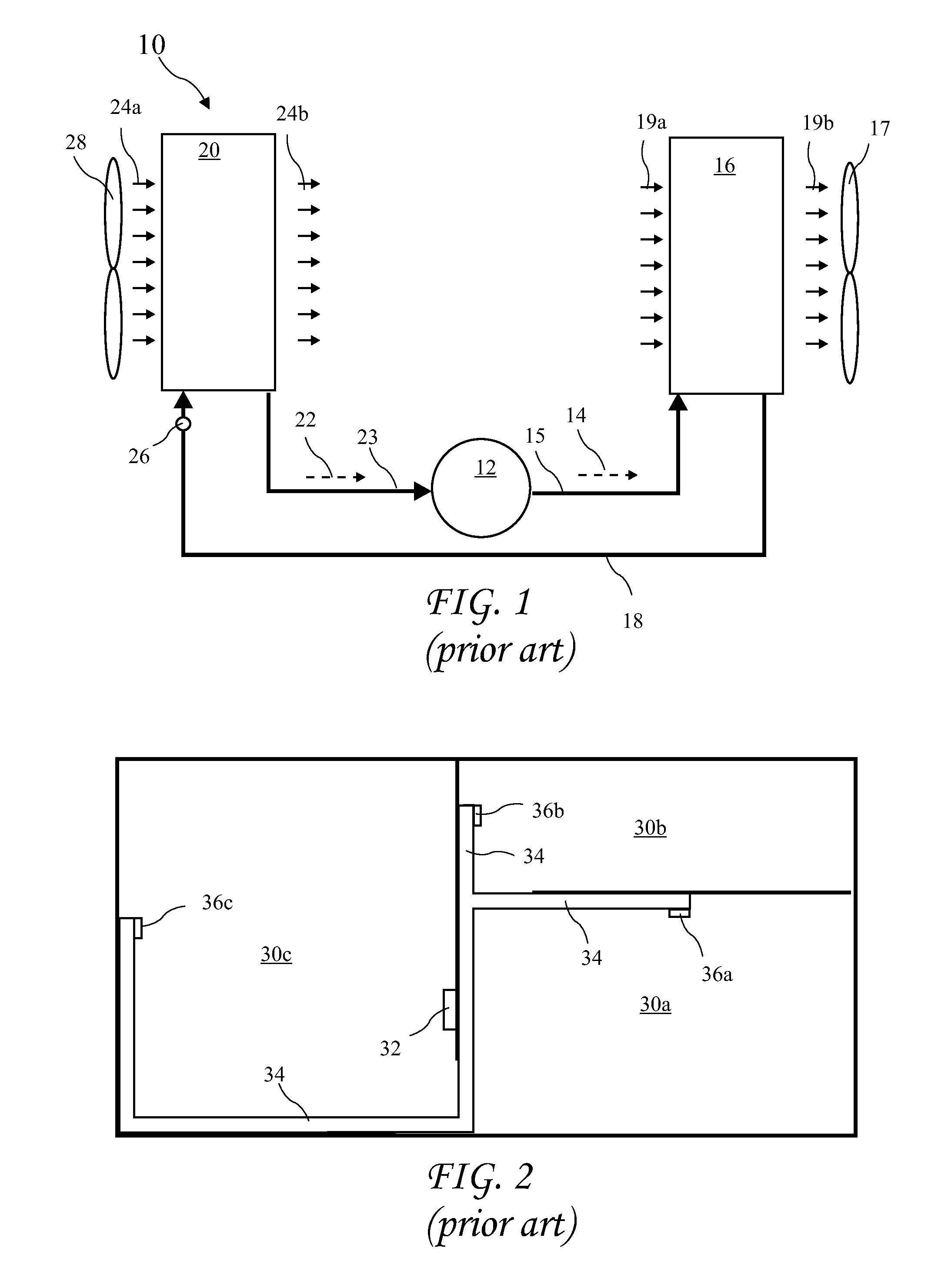
[0032]A diagram showing a known refrigeration and / or air conditioning system 10 is shown in FIG. 1. Typically, the compressor 12 compresses refrigerant into a high-pressure vapor refrigerant flow 14 through a pressure line 15 into a condenser 16. An outdoor fan 17 creates an air flow 19a across the condenser 16 which cools the high-pressure vapor refrigerant flow 14 by removing heat and condenses the high-pressure vapor flow 14 to a liquid state fluid refrigerant flow 18. The heat added to the air flow 19a produces a heated air flow 19b. The liquid state fluid refrigerant flow 18 flows along a refrigerant pipeline, through a metering device 26, an...


PUM


Abstract

An improved chilled beam refrigeration and/or air conditioning systems uses a first chilled air flow to induce a second chilled air flow. Ambient air is drawn through first coils to produce a primary cooled air flow into an intake plenum on the suction side of a fan. The primary cooled air is drawn from the intake plenum, through the fan, and is exhausted into a discharge plenum at a positive pressure. Discharge nozzles along discharge face(s) of the discharge plenum direct the primary cooled air outward inducing a negative pressure in an area behind (or above) second coils. The negative pressure induces additional ambient air to be drawn through the second coils and cooled to provide additional cooled air. The additional cooled air mixes with the primary cooled air providing a larger refrigeration and/or air conditioning effect which would otherwise require additional motorized fans.

Description

BACKGROUND OF THE INVENTION[0001]The present invention relates to refrigeration and / or air conditioning systems and in particular to chilled beam refrigeration and / or air conditioning systems.[0002]Conventional refrigeration and / or air conditioning systems include a central forced air unit with a fan circulating air through coils of an evaporator. The evaporator receives a flow of fluid refrigerant which evaporates into a vapor refrigerant flow out of the evaporator and thereby drops in temperature. The air circulated through the evaporator is cooled and then circulated throughout a house or other structure to provide a flow of cooled air into various areas of the structure. Unfortunately, significant energy is required to circulate the cooled air throughout the structure.[0003]Chilled beam refrigeration systems replace the circulation of the cooled air with circulation of cooled fluid. The cooled fluid is circulated through a radiator (or heat exchanger), generally at a high point ...

Claims


Application Information

Patent Timeline
IPC IPC(8): F28D15/00F24F1/005
CPCF24F1/01F24F1/0007F24F1/005
Inventor WILLIAMS, MICHAEL
Owner WILLIAMS MICHAEL
Why Eureka
Try Eureka