Pyrolysis Apparatus and Methods Using Same

a technology of pyrolysis apparatus and pyrolysis method, which is applied in the direction of lighting and heating apparatus, drying peat, liquid hydrocarbon mixture production, etc., can solve the problems of traditional energy-intensive process, long time-consuming and labor-intensive, and undesirable degradation of landscape by landfills, etc., to achieve cost-effective production and use, simple manufacturing, and useful product

Inactive Publication Date: 2012-09-13
ALL GRADE HLDG
View PDF4 Cites 1 Cited by
  • Summary
  • Abstract
  • Description
  • Claims
  • Application Information

AI Technical Summary

Benefits of technology

[0014]c. a condensing seal through which decomposed gas travels and wherein the condensing seal prevents entry of oxygen into the vessel and egress of heavier compounds out of the vessel.
[0021]Advantages of the apparatus and related methods are that the apparatus is simple to manufacture, cost effective to produce and use and produces a useful product from what is currently a waste product.

Problems solved by technology

Much of the waste plastic ends up in landfills and takes many years to degrade if they ever degrade.
Waste plastic is problematic from an environmental point of view and the degradation of the landscape by landfills is undesirable.
A disadvantage of pyrolysis is that the process is traditionally energy intensive owing to the endothermic nature of the physical and chemical processes involved.

Method used


Image

  • Pyrolysis Apparatus and Methods Using Same
  • Pyrolysis Apparatus and Methods Using Same

Examples


working examples

[0073]Embodiments described above or now described with reference to examples illustrating embodiments of the apparatus and methods of using the apparatus.

example 1

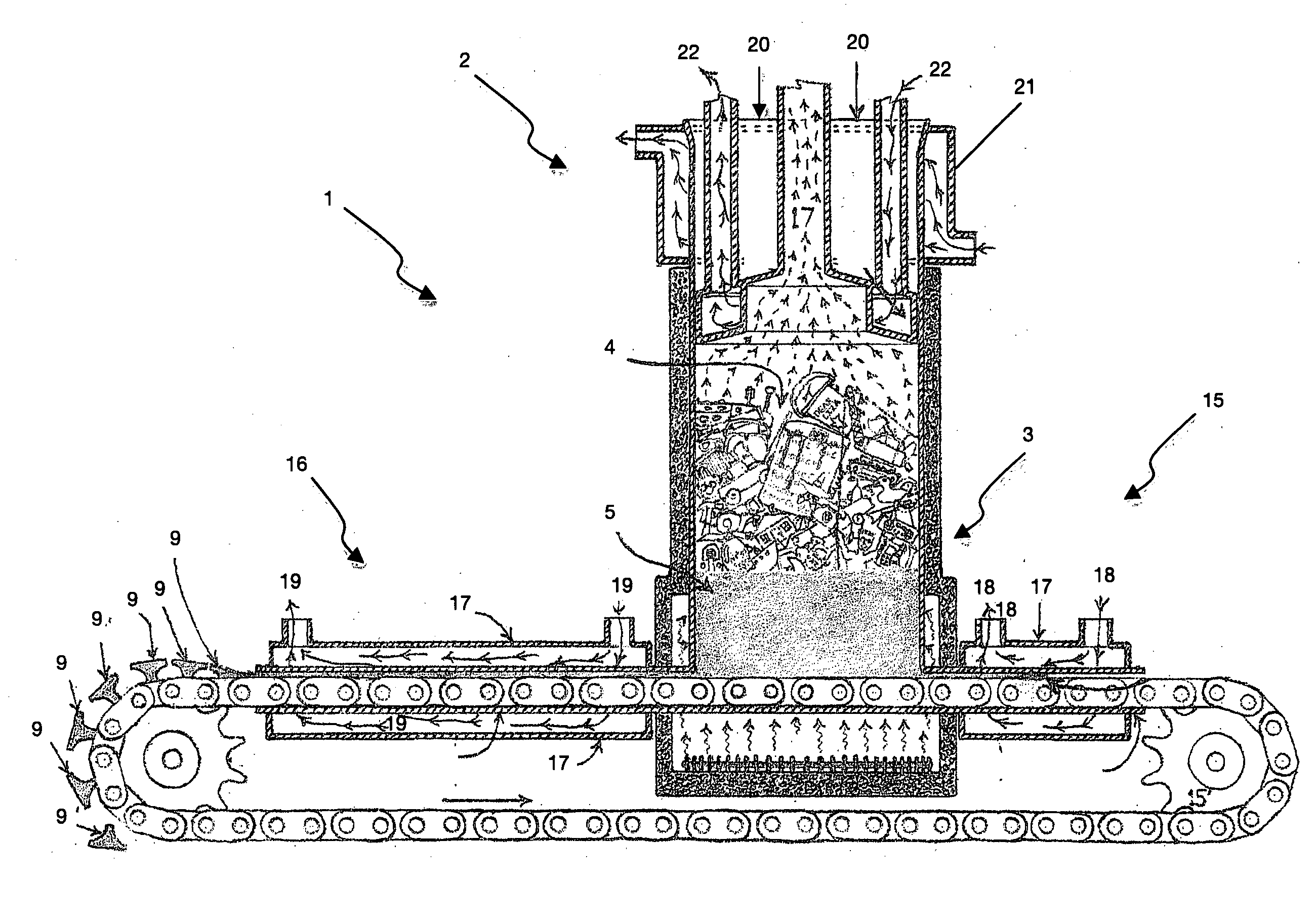
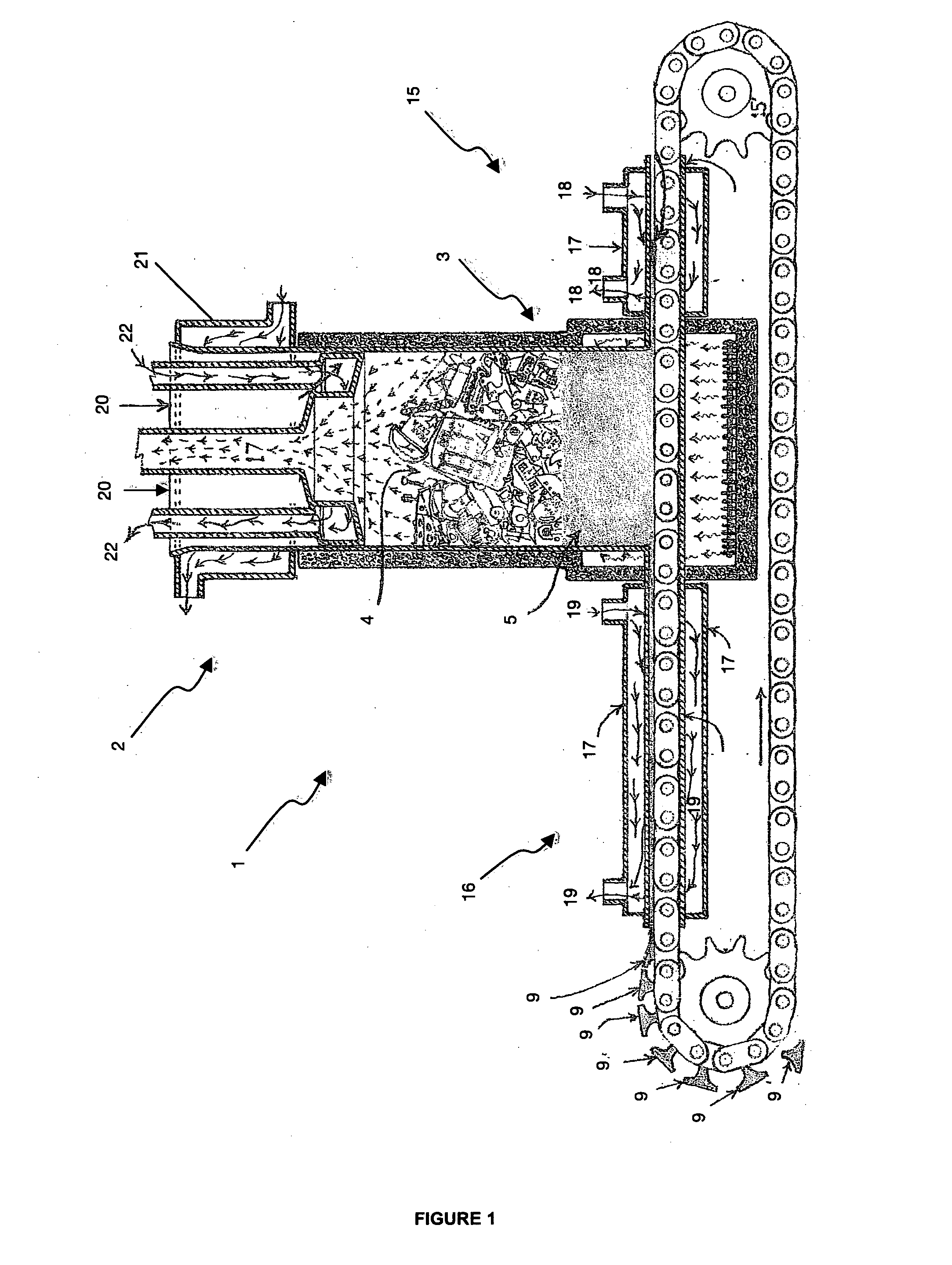
[0074]Referring to FIG. 1, a pyrolysis reactor apparatus 1 is illustrated. The reactor 1 is a cylindrical shaped hollow vessel with a top 2 and bottom 3. The vessel 1 may be insulated as shown by the darkened section in FIG. 1 around the vessel 1 walls. Raw plastic material 4 is fed into the top 2 of the reactor vessel 1. As illustrated in FIG. 1, the raw plastic material 4 may be of any shape or size and no special processing is required prior to adding to the vessel 1. The raw plastic 4 is heated and forms a melted portion 5 at the bottom 3 of the vessel 1. The molten plastic portion 5 decomposes into smaller carbon chains and the resulting gas 6 escapes through the top 2 of the vessel 1 and is collected for further use e.g. as a fuel. Char (not shown) being the solid by-product of the pyrolysis process accumulates at the bottom 3 of the vessel 1 with the molten plastic 5 and is removed from the vessel 1 by the conveyer 7.

[0075]The vessel 1 bottom 3 has a V-shaped cross-section (n...


PUM

PropertyMeasurementUnit
temperatureaaaaaaaaaa

Abstract

An apparatus and methods of using the apparatus are described to decompose plastic to form a fuel for use in generating energy such as electricity.

Description

TECHNICAL FIELD[0001]The application relates to pyrolysis apparatus and methods using same. More specifically, the application relates to an apparatus and methods using the apparatus to decompose plastic and produce fuel for further use in producing energy.BACKGROUND ART[0002]Considerable volumes of plastic waste are produced worldwide. Much of the waste plastic ends up in landfills and takes many years to degrade if they ever degrade. Waste plastic is problematic from an environmental point of view and the degradation of the landscape by landfills is undesirable.[0003]Plastic materials are however made of essentially useful compounds that can be used to generate energy.[0004]Processes are known in the art for processing plastic waste materials by thermochemical breakdown of plastic wastes by combustion, gasification or pyrolysis.[0005]Pyrolysis is the preferred method of performing thermochemical break down of waste plastic materials. By varying conditions of a reactor, the composi...

Claims


Application Information

Patent Timeline
Patent Type & Authority Applications(United States)
IPC IPC(8): C10B7/00C10B57/04
CPCB29B17/04C10G2300/1003C10B1/04C10B47/20C10B53/07C10G1/10C10L5/363C10L5/46F23G2201/303F23G2203/105F23G2204/20F23G2206/203F23G2209/28F23H11/00F23H11/18F23H13/08Y02E50/10Y02E50/30Y02E20/12B29B2017/0496Y02W30/62Y02P20/143B09B3/00C07C4/04C07C4/22
Inventor ROLSTON, PETER JOHN
Owner ALL GRADE HLDG
Why Eureka
Try Eureka