Endplate-preserving spinal implant having a raised expulsion-resistant edge

Active Publication Date: 2012-09-20
TITAN SPINE
View PDF7 Cites 35 Cited by
  • Summary
  • Abstract
  • Description
  • Claims
  • Application Information

AI Technical Summary

Benefits of technology

[0010]The invention is directed to interbody spinal implants and to methods of using such implants. The implants can be inserted, using methods of the invention, from a variety of vantages, including anterior, antero-lateral, and lateral implantation. The spinal implant is preferably adapted to be inserted into a prepared disc space

Problems solved by technology

Over time, the discs may become diseased or infected, may develop deformities such as tears or cracks, or may simply lose structural integrity (e.g., the discs may bulge or flatten).
Impaired discs can affect the anatomical functions of the vertebrae, due to the resultant lack of proper biomechanical support, and are often associated with chronic back pain.
This location is not the preferable seating position for an implant system, however, because only a relatively small portion of the vertebral endplate is contacted by these cylindrical implants.
The seating of these threaded cylindrical implants may also compromise biomechanical integrity by reducing the area in which to distribute mechanical forces, thus increasing the apparent stress experienced by both the implant and vertebrae.
Still further, a substantial risk of implant subsidence (defined as sinking or settling) into the softer cancellous bone of the vertebral body may arise from such improper seating.
Such allograft bone material restricts the usable size and shape of the resultant implant.
Therefore, these cages may not be of a sufficient size to contact the strong cortical bone, or apophyseal rim, of the vertebral endplate.
These size-limited implant systems may also poorly accommodate related

Method used


Image

  • Endplate-preserving spinal implant having a raised expulsion-resistant edge
  • Endplate-preserving spinal implant having a raised expulsion-resistant edge
  • Endplate-preserving spinal implant having a raised expulsion-resistant edge

Examples


Embodiment Construction

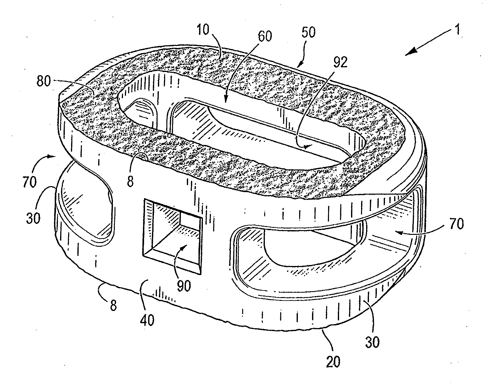
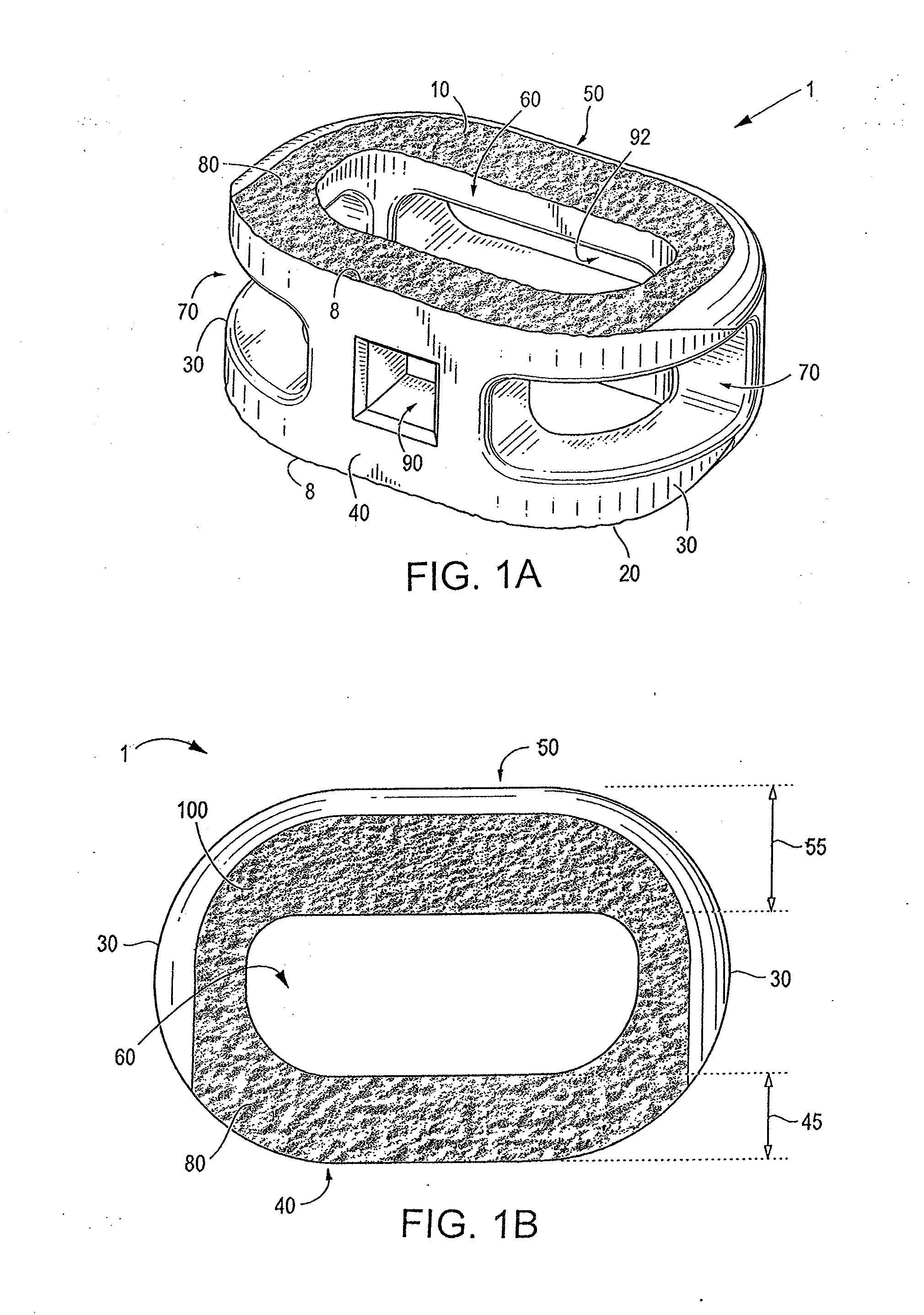
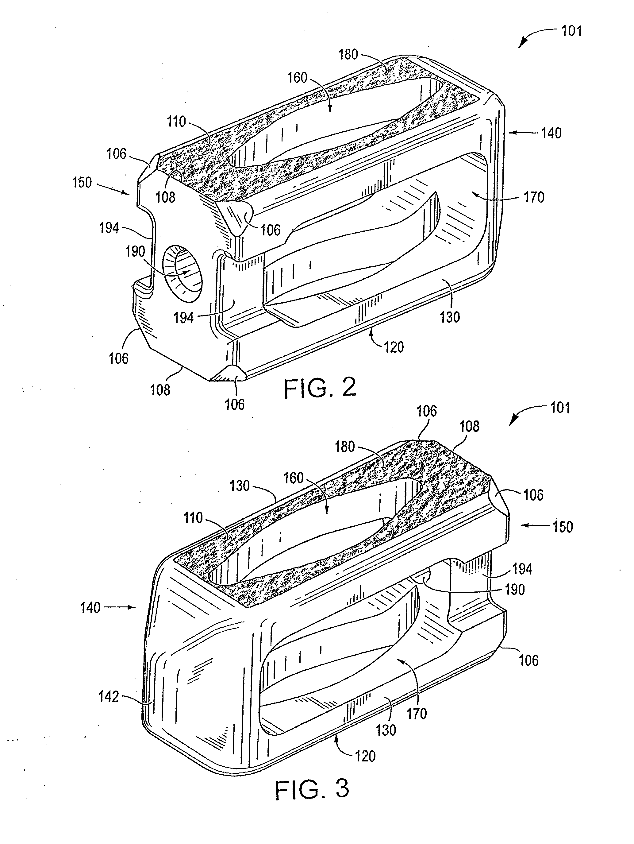
[0117]Certain embodiments of the invention may be especially suited for placement between adjacent human vertebral bodies. The implants of the invention may be used in procedures such as Anterior Lumbar Interbody Fusion (ALIF), Posterior Lumbar Interbody Fusion (PLIF), Transforaminal Lumbar Interbody Fusion (TLIF), and cervical fusion. Certain embodiments do not extend beyond the outer dimensions of the vertebral bodies.

[0118]The ability to achieve spinal fusion is directly related to the available vascular contact area over which fusion is desired, the quality and quantity of the fusion mass, and the stability of the interbody spinal implant. Interbody spinal implants, as now taught, allow for improved seating over the apophyseal rim of the vertebral body. Still further, interbody spinal implants, as now taught, better utilize this vital surface area over which fusion may occur and may better bear the considerable biomechanical loads presented through the spinal column with minimal...


PUM


Abstract

An interbody spinal implant including a body having a top surface, a bottom surface, opposing lateral sides, opposing anterior and posterior portions, a substantially hollow center, and single vertical aperture, as well as an integration plate having a roughened surface topography on its top surface. The integration plate and implant body are joined together with a durable connection.

Description

CROSS REFERENCE TO RELATED APPLICATIONS[0001]This application is a continuation-in-part of U.S. patent application Ser. No. 12 / 151,198, filed on May 5, 2008, and pending, which is a continuation-in-part of U.S. patent application Ser. No. 11 / 123,359, filed on May 6, 2005, and issued as U.S. Pat. No. 7,662,186. The contents of both prior applications are incorporated by reference in this document, in their entirety and for all purposes.FIELD OF THE INVENTION[0002]The invention relates generally to interbody spinal implants and methods of using such implants and, more particularly, to an implant including an anti-expulsion edge on one or more of its anterior, posterior or lateral portions. The anti-expulsion edge may be comprised on the top and / or bottom surface of the implant body itself, or on the top surface of one or more integration plates affixed to the implant body.BACKGROUND OF THE INVENTION[0003]In the simplest terms, the spine is a column made of vertebrae and discs. The ver...

Claims


Application Information

Patent Timeline
IPC IPC(8): A61F2/44
CPCA61F2/30965A61F2002/30507A61F2002/2817A61F2002/2835A61F2002/30014A61F2002/30133A61F2002/30405A61F2002/30604A61F2002/30772A61F2002/30785A61F2002/30836A61F2002/30892A61F2002/30906A61F2002/30925A61F2002/4475A61F2002/448A61F2002/4629A61F2220/0025A61F2230/0015A61F2250/0018A61F2310/00017A61F2310/00023A61F2/447A61F2002/30354A61F2002/30436A61F2002/30448A61F2002/30479A61F2002/30489A61F2002/305A61F2002/30973A61F2/442A61F2002/30112A61F2002/30138A61F2002/30148A61F2002/30153A61F2002/30154A61F2002/30156A61F2002/30164A61F2002/30441A61F2002/30454A61F2002/30469A61F2002/30472A61F2002/30481A61F2/4465A61F2002/30433A61F2002/30451A61F2002/30487A61F2002/30593
Inventor ULLRICH, JR., PETER F.PATTERSON, CHAD J.
Owner TITAN SPINE
Why Eureka
Try Eureka