Multi-diameter optical fiber link for transmitting unidirectional signals and eliminating signal deterioration

a multi-diameter, optical fiber technology, applied in the field of optical fiber links, can solve the problems of accumulating distortion, serious distortion of optical signals received by optical signal receiving chips, and detrimental to the quality of optical signal transmission, and achieve the effect of eliminating signal deterioration

Inactive Publication Date: 2012-09-27
NETGAMI SYST
View PDF23 Cites 1 Cited by
  • Summary
  • Abstract
  • Description
  • Claims
  • Application Information

AI Technical Summary

Benefits of technology

[0030]FIG. 9 schematically shows the structure of a multi-diameter optical fiber link for transmitting unidirectional signals and eliminating signal deterioration according to the seventh preferred embodiment of the present invention.

Problems solved by technology

While signal distortion over a short distance is only nominal, the accumulated distortion over a long distance can be detrimental to the quality of optical signal transmission.
Now that attenuation is a major factor that hinders the transmission of optical signals over long distances, it is an important issue in the optical fiber industry to reduce signal attenuation.
Consequently, the optical signals received by the optical signal receiving chip are seriously distorted.
This leads to significant distortion of the optical signals received by the optical signal receiving chip.
This also causes serious distortion to the optical signals received by the optical signal receiving chip.
This approach, however, significantly increases the manufacturing cost and complexity of cable adaptors, which prevents the ceramic ferrules from general application to consumer electronic products as a device that assists in high-speed transmission of large audio / video streams.
Furthermore, should the manufacture or assembly of such ceramic ferrules be defective, cables connected thereby will still suffer from the aforesaid misalignment problems in which the optical fibers are not properly aligned along the same axis.

Method used


Image

  • Multi-diameter optical fiber link for transmitting unidirectional signals and eliminating signal deterioration
  • Multi-diameter optical fiber link for transmitting unidirectional signals and eliminating signal deterioration
  • Multi-diameter optical fiber link for transmitting unidirectional signals and eliminating signal deterioration

Examples


Embodiment Construction

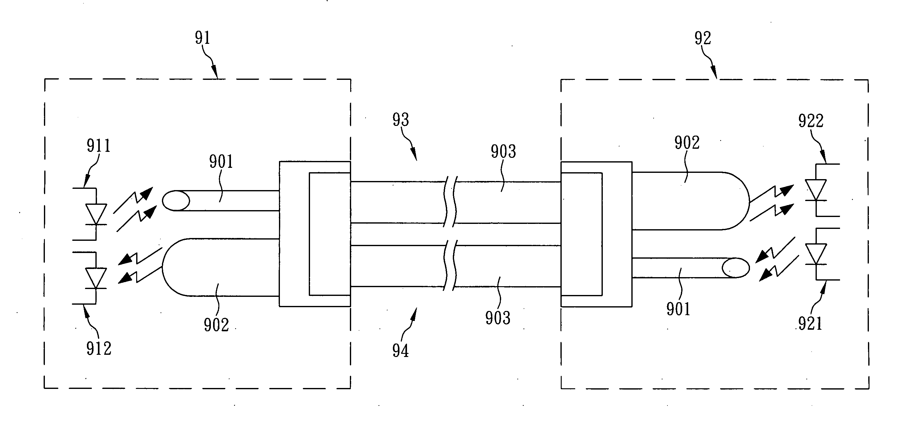
[0031]Referring to FIG. 7, the present invention provides a multi-diameter optical fiber link 70 for transmitting unidirectional signals and eliminating signal deterioration, wherein the multi-diameter optical fiber link 70 includes a first cable 701 and a second cable 702. The first cable 701 encloses a first optical fiber 7011 therein. The first optical fiber 7011 has a first end surface for receiving optical signals and transmitting the received optical signals to a second end surface of the first optical fiber 7011. The first cable 701 has a second end which corresponds in position to the second end surface of the first optical fiber 7011 and which is peripherally and fixedly provided with a first adaptor 7012. The second cable 702 encloses a second optical fiber 7021 therein. The second optical fiber 7021 has a first end surface for receiving optical signals and transmitting the received optical signals to a second end surface of the second optical fiber 7021. The second cable ...


PUM


Abstract

The present invention is to provide a multi-diameter optical fiber link, which includes a first cable and a second cable connected in series with the first cable through an adaptor (or adaptors) and is characterized in that a first optical fiber enclosed in the first cable has a smaller diameter than a second optical fiber enclosed in the second cable. Hence, when the first and second cables are connected in series, an end surface of the first optical fiber is easily and precisely aligned within an end surface of the second optical fiber, thus allowing the second optical fiber to receive all optical signals transmitted from the first optical fiber. Consequently, the optical signals pass through the first and second optical fibers in succession, and a unidirectional signal transmission is realized in the multi-diameter optical fiber link without signal deterioration which may otherwise result from misalignment of the optical fibers.

Description

FIELD OF THE INVENTION[0001]The present invention relates to an optical fiber link, more particularly to a multi-diameter optical fiber link for transmitting unidirectional signals and eliminating signal deterioration.BACKGROUND OF THE INVENTION[0002]Optical fibers are glass or plastic fibers designed to transmit optical signals via total reflection of light within each fiber. Referring to FIG. 1, a thin optical fiber 11 is surrounded by and enclosed in a plastic sheath 12 to form a cable 10, wherein the resilience and mechanical strength of the plastic sheath 12 allow the optical fiber 11 to bend without breaking. After an end surface of the optical fiber 11 receives an optical signal generated by an optical signal transmitting chip 13 (e.g., a laser diode), the optical signal travels along the optical fiber 11 and finally reaches an opposite end surface thereof, so as for an optical signal receiving chip 14 (e.g., a photo diode) connected to the latter end surface of the optical f...

Claims


Application Information

Patent Timeline
Patent Type & Authority Applications(United States)
IPC IPC(8): G02B6/26
CPCG02B6/3825G02B6/02033
Inventor LYNN, JOHN
Owner NETGAMI SYST
Why Eureka
Try Eureka