Stratified two-stroke engine and dual passage fuel system

a fuel system and two-stroke technology, applied in the direction of heating types, separation processes, applications, etc., can solve the problems of affecting the efficiency of the engine, the inability to use the same design in the chainsaw, and the inability to extend the operation of the engine upside down for extended time, so as to reduce the emissions. the effect of significant reduction

a fuel system and two-stroke technology, applied in the direction of heating types, separation processes, applications, etc., can solve the problems of affecting the efficiency of the engine, the inability to use the same design in the chainsaw, and the inability to extend the operation of the engine upside down for extended time, so as to reduce the emissions. the effect of significant reduction

US20120247435A1Inactive Publication Date: 2012-10-04MAVINAHALLY NAH S

Image

  • Stratified two-stroke engine and dual passage fuel system
  • Stratified two-stroke engine and dual passage fuel system
  • Stratified two-stroke engine and dual passage fuel system

Examples


Embodiment Construction

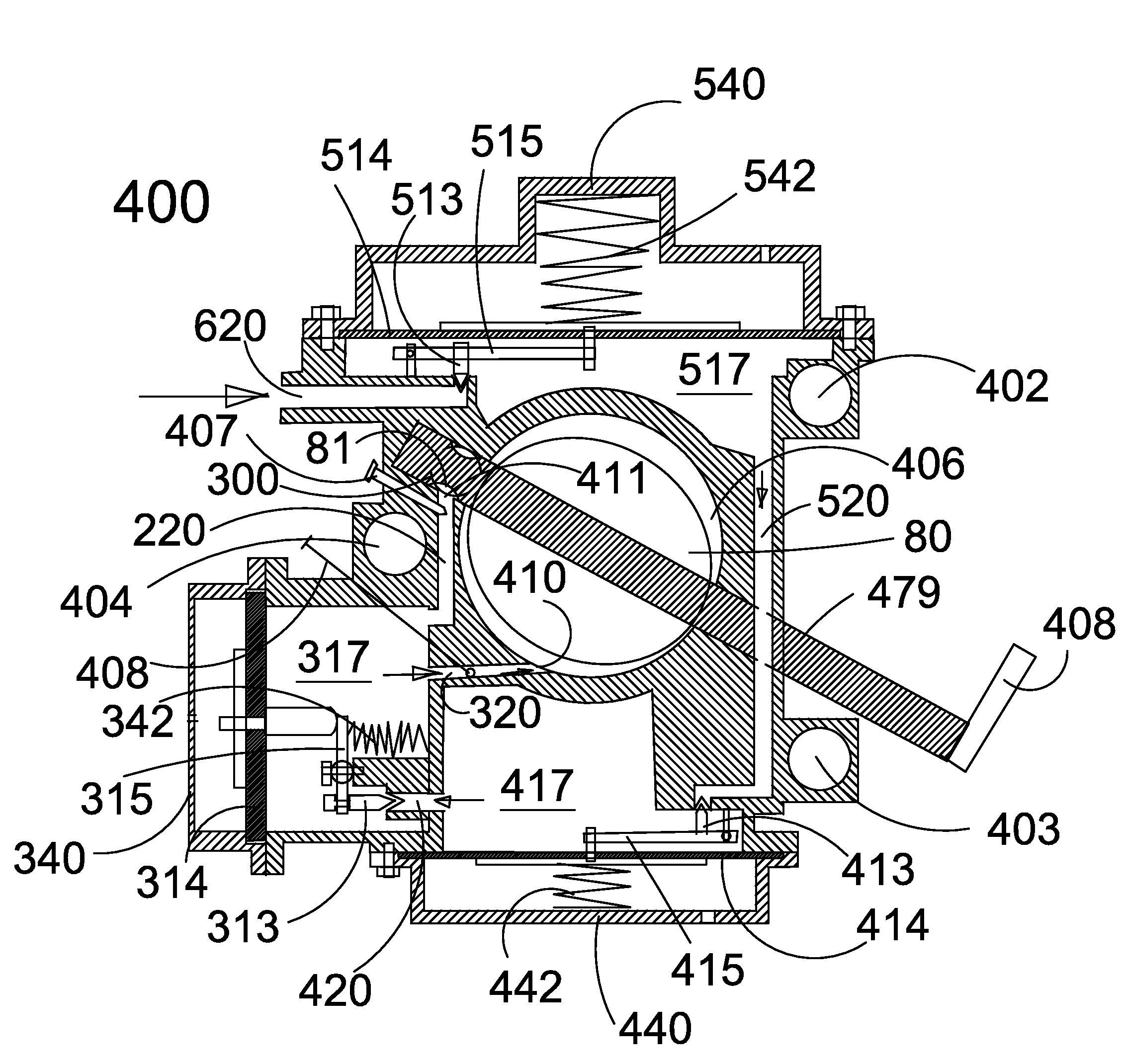
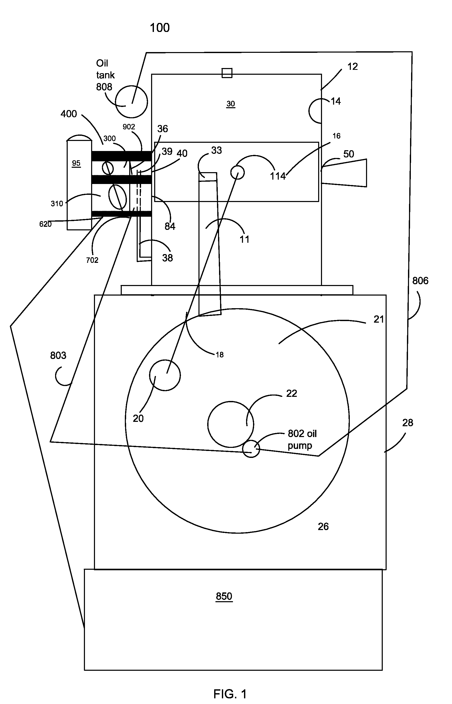
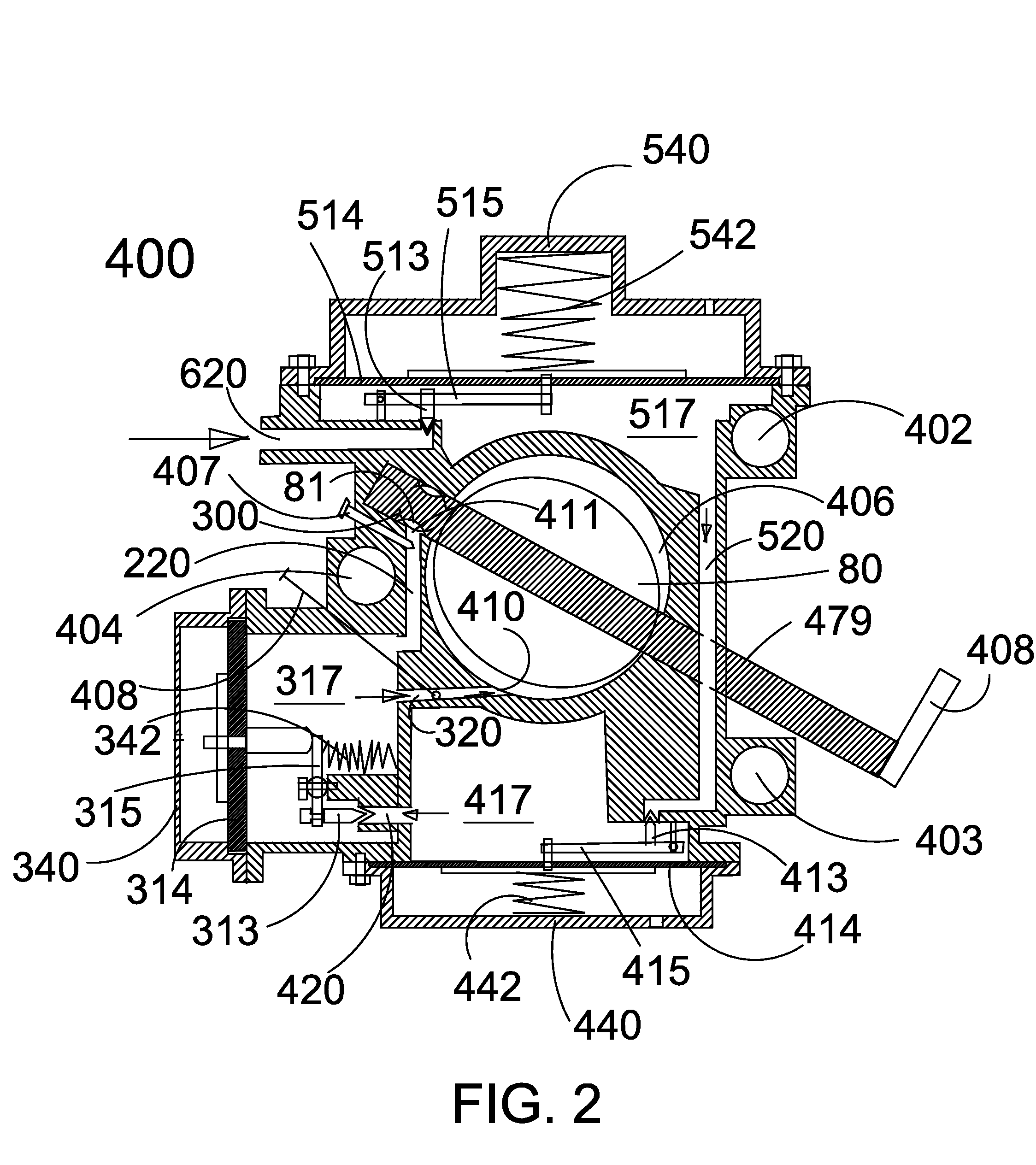
[0035]FIGS. 1, through 6 show new two-stroke gaseous fueled oil injected engines with special gaseous fueled carburetors having built in pressure regulator and metering chambers. The two-stroke engine are of stratified type having either a rich charge tube or air-head scavenging as described in U.S. Pat. Nos. 6,901,892, 4,253,433, and 6,273,037. The draw back in the prior arts are that the engines employ gasoline as fuel and oil has to be pre-mixed. The gaseous fuel two-stroke engine made by Mitsubishi as described in U.S. Pat. No. 5,918,574 is not a stratified engine, hence has significantly higher emission levels. The most commonly used gaseous fueled carburetors are not suitable for stratified engines. There are, however, gasoline fueled stratified carburetors, but they are not made to handle gaseous fuels. Therefore it is believed by the inventors that the inventions disclosed here would be beneficial to help the environment and reduce dependence on liquid fuels.

[0036]U.S. Pat. ...


PUM

PropertyMeasurementUnit
Timeaaaaaaaaaa
Timeaaaaaaaaaa
Pressureaaaaaaaaaa

Abstract

Various embodiments include two-stroke stratified engines and dual passage carburetors for use with gaseous fuel, such as hydrogen, methane, liquid petroleum gas, pure propane, and butane. A stratified air-head engine and low pressure fuel injected engines with fuel only tube is included.

Description

RELATED APPLICATIONS[0001]The present application claims the benefit of priority of U.S. provisional application Nos. 61 / 313,801, filed Mar. 14, 2010, entitled “STRATIFIED TWO-STROKE ENGINE AND FUEL SYSTEM”, 61 / 471,182, filed Apr. 3, 2011, entitled “STRATIFIED TWO-STROKE ENGINE' and 61 / 494,417, filed Jun. 8, 2011, entitled “STRATIFIED TWO-STROKE ENGINE AND FUEL SYSTEM”, the entirety of which is incorporated by reference herein for all purposes.BACKGROUND[0002]Conventional gasoline fueled four-stroke engine used in hand-held applications as in a trimmer and a blower sold by Ryobi and MTD and gaseous fueled blower by LEHR are environmentally friendly. However, the drawback is that those engines are very heavy and cannot be operated upside down for extended time and the same design cannot be used in chainsaws. Alternative two-stroke engines are advantageous, but very high in emission levels. Gaseous fueled two-stroke trimmer engine as manufactured and sold by Mitsubishi is a convention...

Claims


Application Information

Patent Timeline
04 Oct 2012
Publication
US20120247435A1
IPC
F02M7/23; F02M9/02
CPC
F02M7/225; F02M13/08; Y02T10/32; F02M21/042; F02M17/04; Y02T10/30
Inventors
VEERATHAPPA, JAY S.; MAVINAHALLY, NAGESH S.