Brush holder assemblies

a brush holder and assembly technology, applied in current collectors, dynamo-electric machines, electrical apparatus, etc., can solve the problems of difficult brush maintenance, difficult brush cooling, and unsupported brush portions, so as to improve the functionality of existing brush holder assemblies, promote cooling, and reduce surface area

Active Publication Date: 2013-02-14
WABTEC HLDG CORP
View PDF7 Cites 0 Cited by
  • Summary
  • Abstract
  • Description
  • Claims
  • Application Information

AI Technical Summary

Benefits of technology

[0005]The present invention improves functionality of existing brush holder assemblies. Unlike conventional such assemblies, those of the present invention provide rails, rather than boxes, for supporting brushes. The rails may cover substantially less surface area of brushes than do boxes, promoting cooling when the brushes are in use and facilitating maintenance when they are not in use. The rails additionally may extend along, and thereby support, entire lengths of the brushes.

Problems solved by technology

For example, brush cooling may be difficult when boxes are used, as the boxes cover much of the surface area of the brushes.
Likewise brush maintenance may be difficult because of the surface-area coverage of the boxes.
Conversely, because boxes do not typically extend the entire length of brushes (at least when new), they leave portions of the brushes unsupported.

Method used


Image

  • Brush holder assemblies
  • Brush holder assemblies
  • Brush holder assemblies

Examples


Embodiment Construction

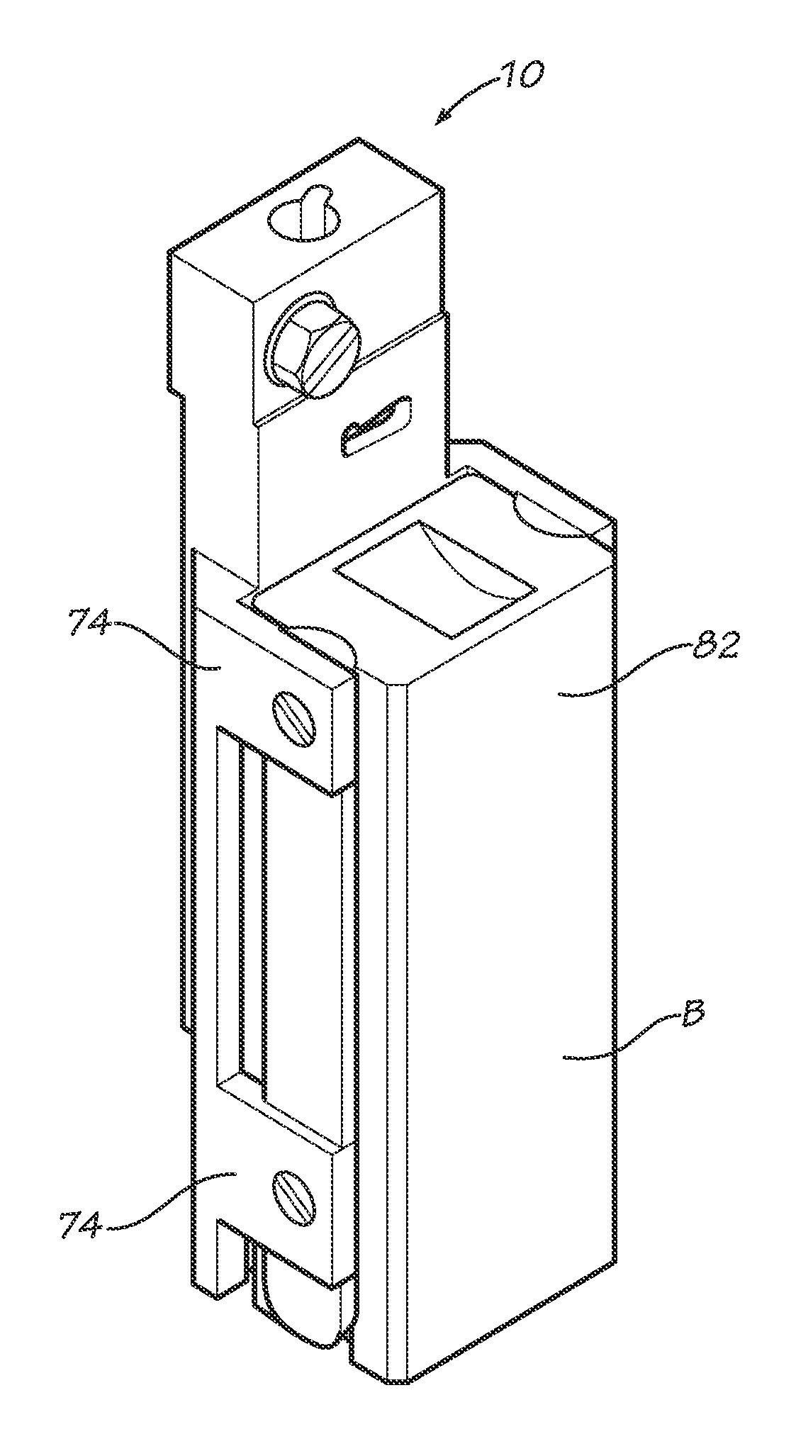
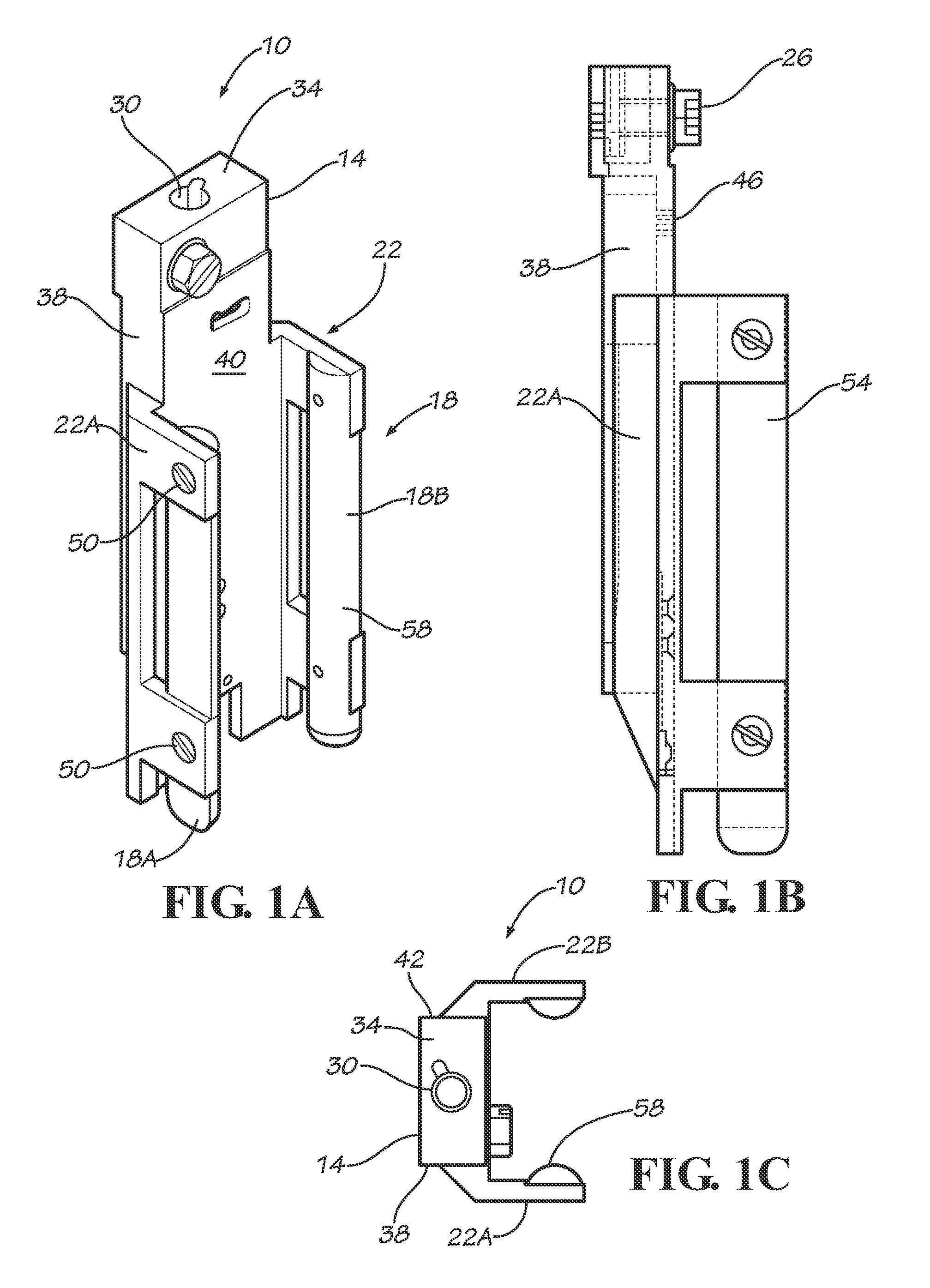
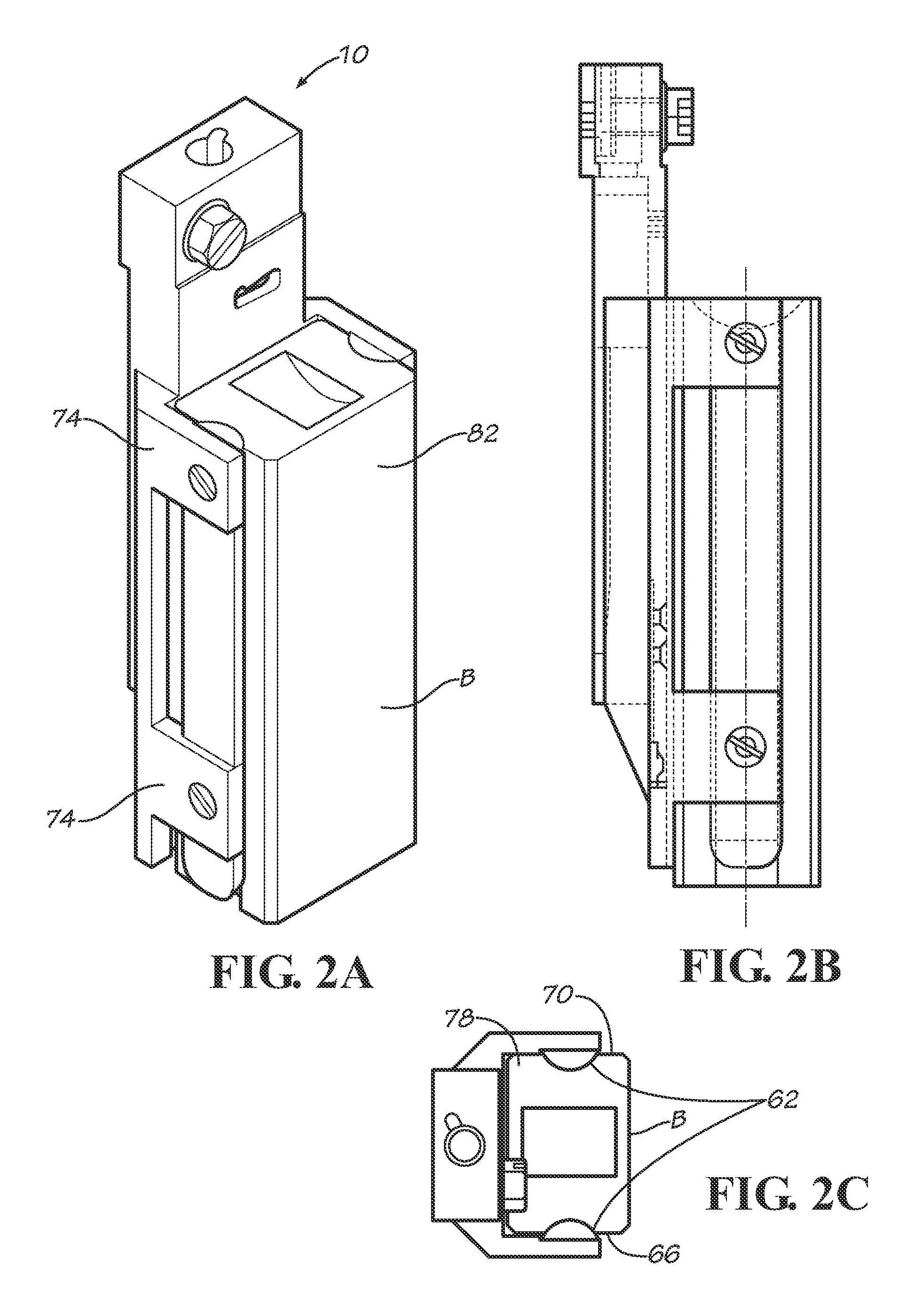
[0021]Depicted in FIGS. 1A-C is a version of brush holder assembly 10. Assembly 10 may comprise plate or body 14, rails 18, and rail supports 22. It also may include an electrical connector, shown as being terminal screw 26, and optionally a bore 30 for receiving a handle (for example).

[0022]Body 14 may be elongate and configured for connection to another object. It may (but need not necessarily) be generally rectangular in shape and define nominally top surface 34 (in which bore 30 may be formed), first and second sides 38 and 42, respectively, and face 46 spanning the sides 38 and 42. One or more elongate supports 22 may connect to one or more of sides 38 and 42. As shown in FIGS. 1A-C, support 22A connects to side 38, whereas support 22B connects to side 42. Such connection may occur in any appropriate manner, or supports 22 may be integrally formed with body 14.

[0023]Attached to each support 22 may be rail 18. Each rail 18 too is elongate and preferably of length exceeding—or at...


PUM


Abstract

Brush holder assemblies are detailed. The assemblies may employ rails, rather than boxes, for supporting brushes. They additionally may extend along all, or substantially all, of the lengths of the brushes for enhanced support of the brushes.

Description

CROSS-REFERENCE TO RELATED APPLICATION[0001]This application claims the benefit of U.S. Provisional Application Ser. No. 61 / 574,740, filed Aug. 8, 2011, titled “Brush Holder-Rail Support System,” the entire contents of which are hereby incorporated by reference.FIELD OF THE INVENTION[0002]This invention relates to brush holders and associated equipment and more particularly, although not necessarily exclusively, to brush holder assemblies having rails for supporting brushes.BACKGROUND OF THE INVENTION[0003]Commonly-owned U.S. Pat. No. 7,365,470 to Eger, et al., the contents of which are incorporated herein by this reference, describes and illustrates innovative brush holder assemblies. Included as part of such a brush holder may be a brush box designed to support and restrain some movement of a brush during operation of a rotating device such as a commutator or a slip ring. In this sense the brush holder is conventional, as brush boxes generally are commonly used to support brushes....

Claims


Application Information

Patent Timeline
Patent Type & Authority Applications(United States)
IPC IPC(8): H01R39/40
CPCH01R39/40
Inventor EGER, LEO A.PARSLOW, JOHN
Owner WABTEC HLDG CORP
Why Eureka
Try Eureka