Wearable Fan Assembly And A Method Including The Same

Inactive Publication Date: 2013-05-02
HOYE LAWRENCE G
View PDF11 Cites 23 Cited by
  • Summary
  • Abstract
  • Description
  • Claims
  • Application Information

AI Technical Summary

Benefits of technology

[0021]In yet another preferred embodiment, a top surface of the curved plate is substantially flush with a top surface of the metallic material along at

Problems solved by technology

Although, especially during the summer season in warmer climates, crowded outdoor stadiums tend to get uncomfortably hot for many of their spectators.
In addition to the hot temperatures, stagnant conditions resulting from the lack of air movement in the large, semi-enclosed structures further increase the thermal discomfort experienced by the spectators located therein.
Presently, there is no practical way to effectively cool spectators in such a crowded environment.
The typical systems that are used to condition the air in the interior spaces of buildings cannot be reasonably applied to large, open-air sta

Method used


Image

  • Wearable Fan Assembly And A Method Including The Same
  • Wearable Fan Assembly And A Method Including The Same
  • Wearable Fan Assembly And A Method Including The Same

Examples


Example

[0059]Throughout the figures, the same parts are always denoted using the same reference characters so that, as a general rule, they will only be described once.

DETAILED DESCRIPTION OF THE PREFERRED EMBODIMENT(S) OF THE INVENTION

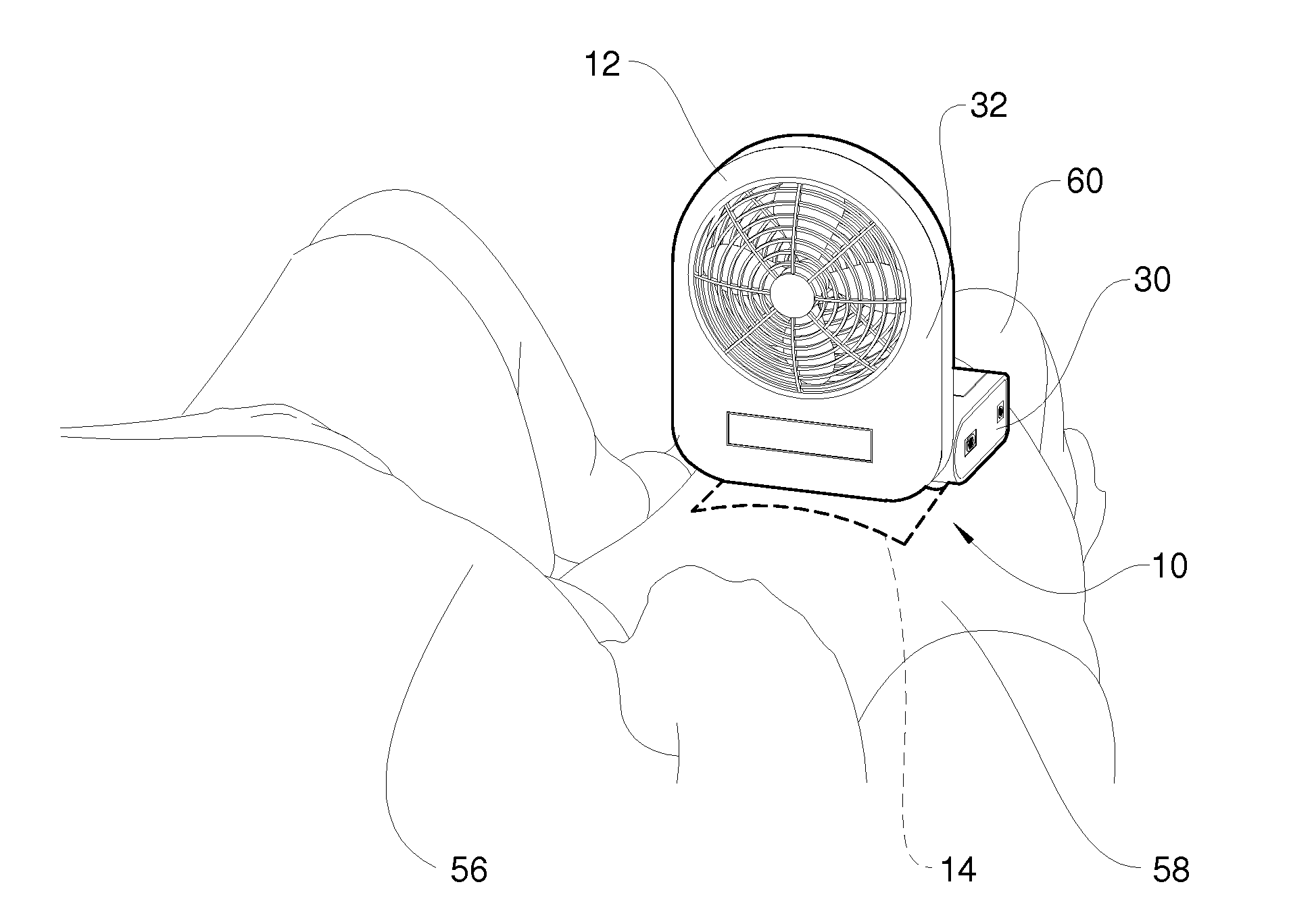
[0060]An embodiment of the wearable fan assembly is seen generally at 10 in FIG. 16. The wearable fan assembly 10 of the depicted embodiment principally comprises a fan portion 12 and a detachable component 14. As shown in FIG. 16, and more explicitly in the sectional view of FIG. 18, the fan portion 12 engages the detachable component 14 in such a manner that a piece of fabric 16 (preferably a portion of the clothing on a user) is sandwiched between the fan portion 12 and the detachable component 14. In a preferred embodiment of the invention, the wearable fan assembly 10 is configured to be attached to an article of clothing worn by a user thereof.

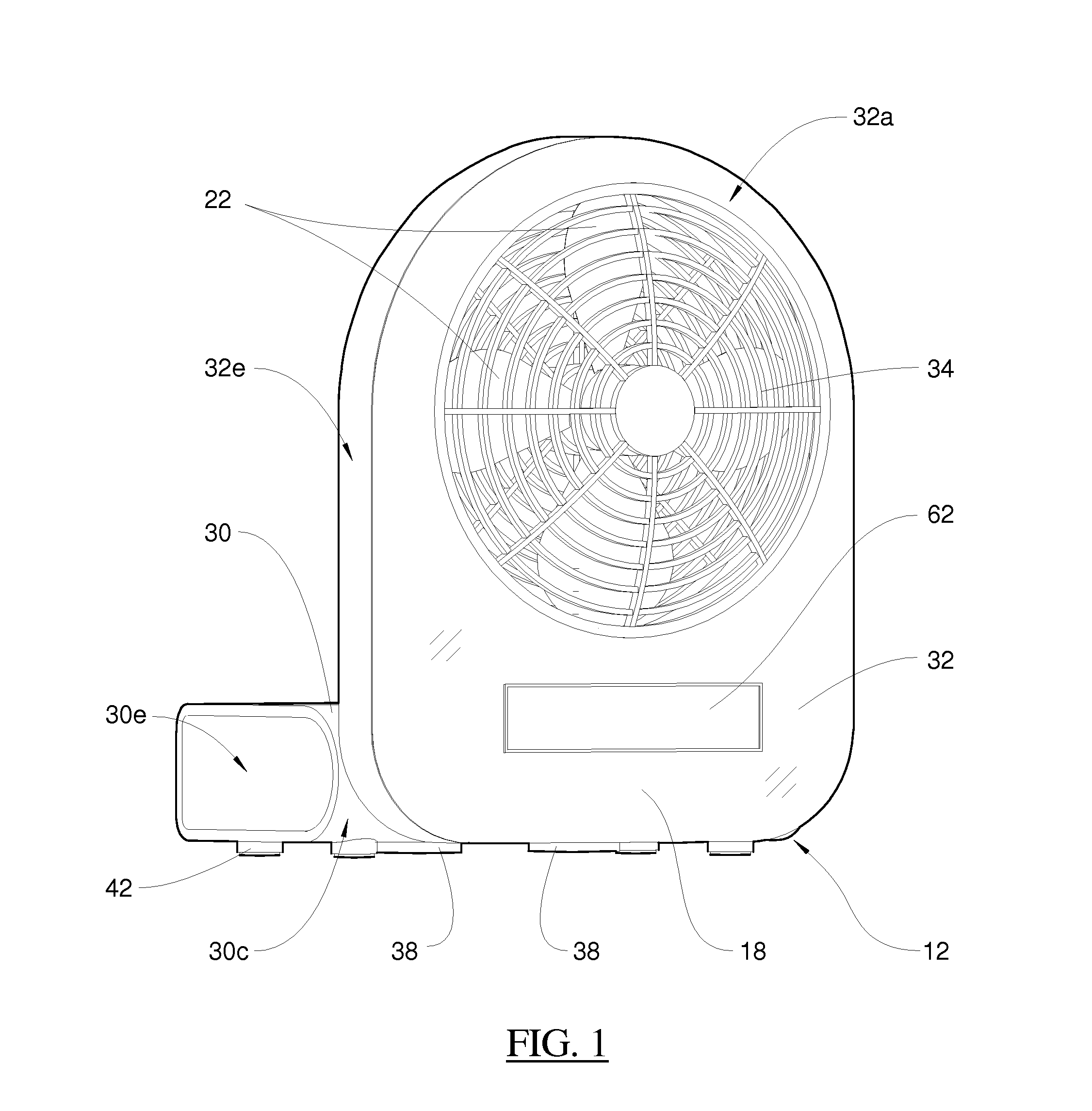
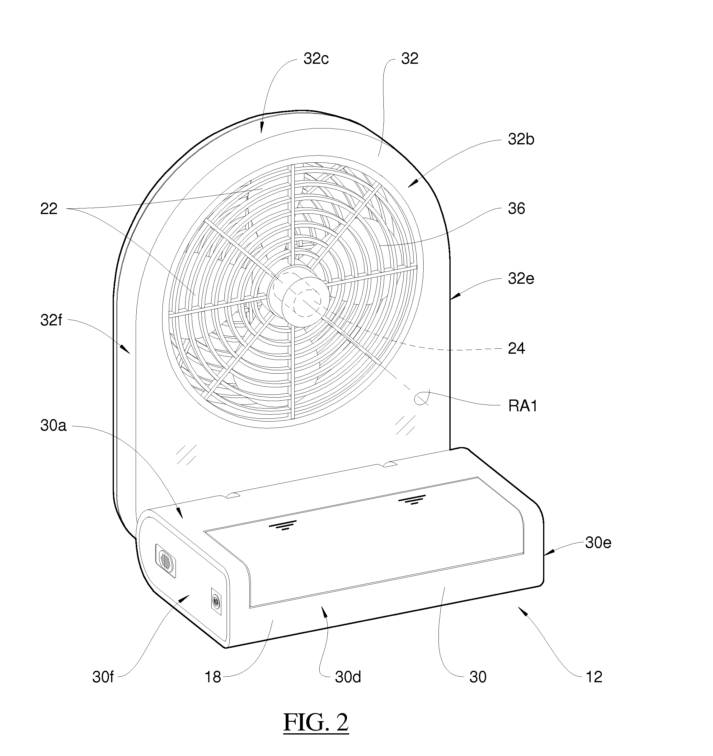
[0061]Referring to FIGS. 1-4 and 9-10, it can be seen that the fan portion 12 (also referred to herein as fan ...


PUM

PropertyMeasurementUnit
Flow rateaaaaaaaaaa
Sizeaaaaaaaaaa
Flexibilityaaaaaaaaaa

Abstract

A wearable fan assembly including a fan housing having a base portion, the base portion having a bottom surface with at least one magnet disposed thereon; a power source disposed in the base portion of the fan housing; a plurality of fan blades pivotally disposed about a rotational axis; a motor for driving the fan blades during an operational state of the fan assembly, the motor operatively coupled to the power source in the base portion of the fan housing; and a detachable component configured to matingly engage with the at least one magnet disposed on the bottom surface of the base portion of the fan housing. When the wearable fan assembly is attached to an article of clothing worn by a user, a portion of the article of clothing is sandwiched between a bottom surface of the at least one magnet and a top surface of the detachable component.

Description

CROSS-REFERENCE TO RELATED APPLICATIONS[0001]This patent application claims priority to, and incorporates by reference in its entirety, pending U.S. Provisional Patent Application No. 61 / 552,393, entitled “Wearable Fan Assembly And A Method Including The Same”, filed on Oct. 27, 2011.STATEMENT REGARDING FEDERALLY SPONSORED RESEARCH OR DEVELOPMENT[0002]Not Applicable.NAMES OF THE PARTIES TO A JOINT RESEARCH AGREEMENT[0003]Not Applicable.INCORPORATION BY REFERENCE OF MATERIAL SUBMITTED ON A COMPACT DISK[0004]Not Applicable.BACKGROUND OF THE INVENTION[0005]1. Field of the Invention[0006]The invention generally relates to wearable fan devices. More particularly, the invention relates to a wearable fan assembly that is configured to be attached to an article of clothing worn by a user, and a method including the same.[0007]2. Background and Related Art[0008]Throughout the world, outdoor spectator sports are enjoyed by millions of exuberant fans every year. Although, especially during the...

Claims


Application Information

Patent Timeline
IPC IPC(8): F04D19/00B23P11/00
CPCY10T29/49826F04D25/084F04D29/601
Inventor HOYE, LAWRENCE G.
Owner HOYE LAWRENCE G
Why Eureka
Try Eureka