Medical instrument holding apparatus

Inactive Publication Date: 2015-02-12
SEIKO EPSON CORP
View PDF3 Cites 0 Cited by
  • Summary
  • Abstract
  • Description
  • Claims
  • Application Information

AI Technical Summary

Benefits of technology

[0024](12) The medical instrument holding apparatus may include a replacement housing unit which houses a part including at least a distal end of a replaceable replacement member provided on the medical instrument, in order to replace the replacement member, and a detachment unit which detaches the replacement member housed in the replacement housing unit from the instrument. In this medical instrument holding apparatus, the replacement member provided at a distal end of a medical instrument can be easily detached, using the medical instrument holding apparatus. Particularly, since the operator need not touch other members for the replacement, the replacement member can be detached more safely.
[0025](13) Here, the medical instrument holding apparatus may further include a new replacement member installed on the instrument instead of the detached replacement member, and a replacement member installing unit which houses the new replacement member in such a way that the new replacement member can be installed on the instrument. Thus, the replacement member can be replaced with a new member, using the medical instrument holding apparatus. In this case, since the operator need not touch other members, the replacement member can be replaced more safely.
[0026](14) When at least apart of a liquid ejection device is housed as a medical instrument in the medical instrument holding apparatus, with the function of the coordination unit, a predetermined discharge operation to discharge a liquid from inside a liquid chamber can be executed on the side of the liquid ejection device. Since the gas inside the liquid chamber is discharged with the liquid, the operator need not carry out any work to discharge the gas from inside the liquid ch

Problems solved by technology

However, since a functional unit to realize various functions is assembled in the medical instrument, simply preparing the stand to hold the medical instrument upright does not provide a sufficient solution.
The medical instrument has various constraints due to the functions thereof.
For example, in an operating theater, no contamination from the patient is allowed and therefore basically the instrument used for the operation must not be reused.
However, how to determine whether the stand is already used or not is not considered so far.
Similarly, there are many unresolved problems with the holding apparatu

Method used


Image

  • Medical instrument holding apparatus
  • Medical instrument holding apparatus
  • Medical instrument holding apparatus

Examples


Example

1 First Embodiment

Configuration of Apparatus

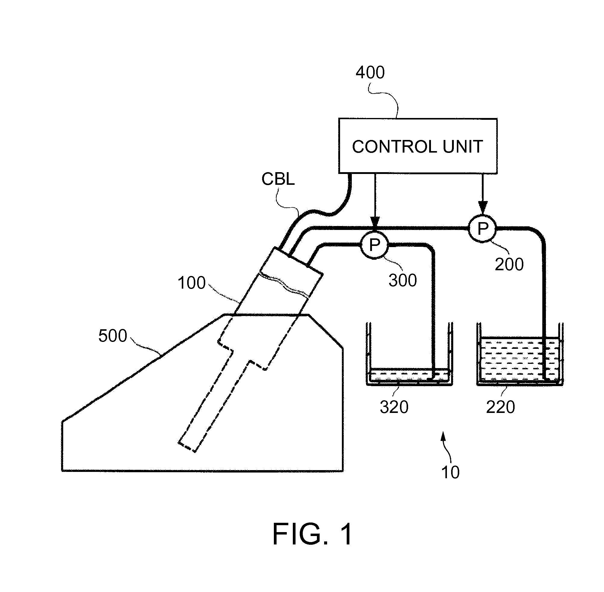
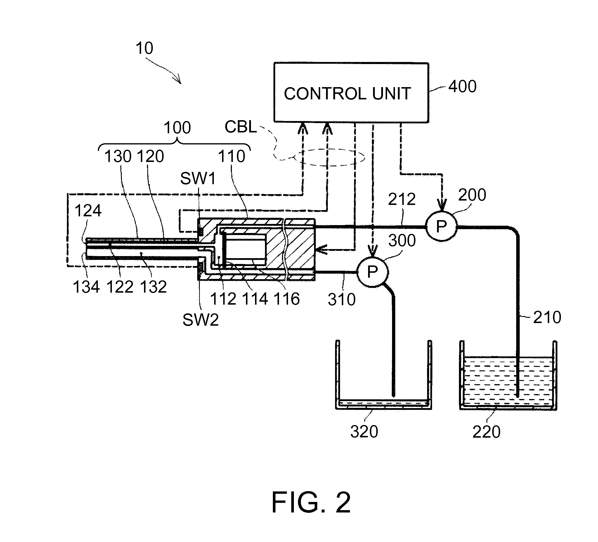
[0053]FIG. 1 is a schematic configuration view showing the state where a liquid ejection device 100 is installed on a stand 500 that is a medical instrument holding apparatus according to a first embodiment of the invention. As illustrated, in terms of electric system, the liquid ejection device 100 is connected to a control unit 400 via a cable CBL. In terms of fluid system, the liquid ejection device 100 is connected to a liquid container 220 and a drainage container 320 via tubes. The supply and discharge of a liquid is carried out by a feed pump 200 and a suction pump 300 with the operations thereof controlled by the control unit 400. The communication of signals between the liquid ejection device 100 and the control unit 400, and the supply and discharge of the liquid under the control of the control unit 400 will be described in detail later. The overall configuration including the liquid ejection device 100, the control unit 400 and...

Example

2 Second Embodiment

[0081]Hereinafter, a second embodiment of the invention will be described. The description focuses on different parts from the liquid ejection device system 10 of the first embodiment. Similar configurations to those of the first embodiment are denoted by the same reference numerals and will not be described further in detail.

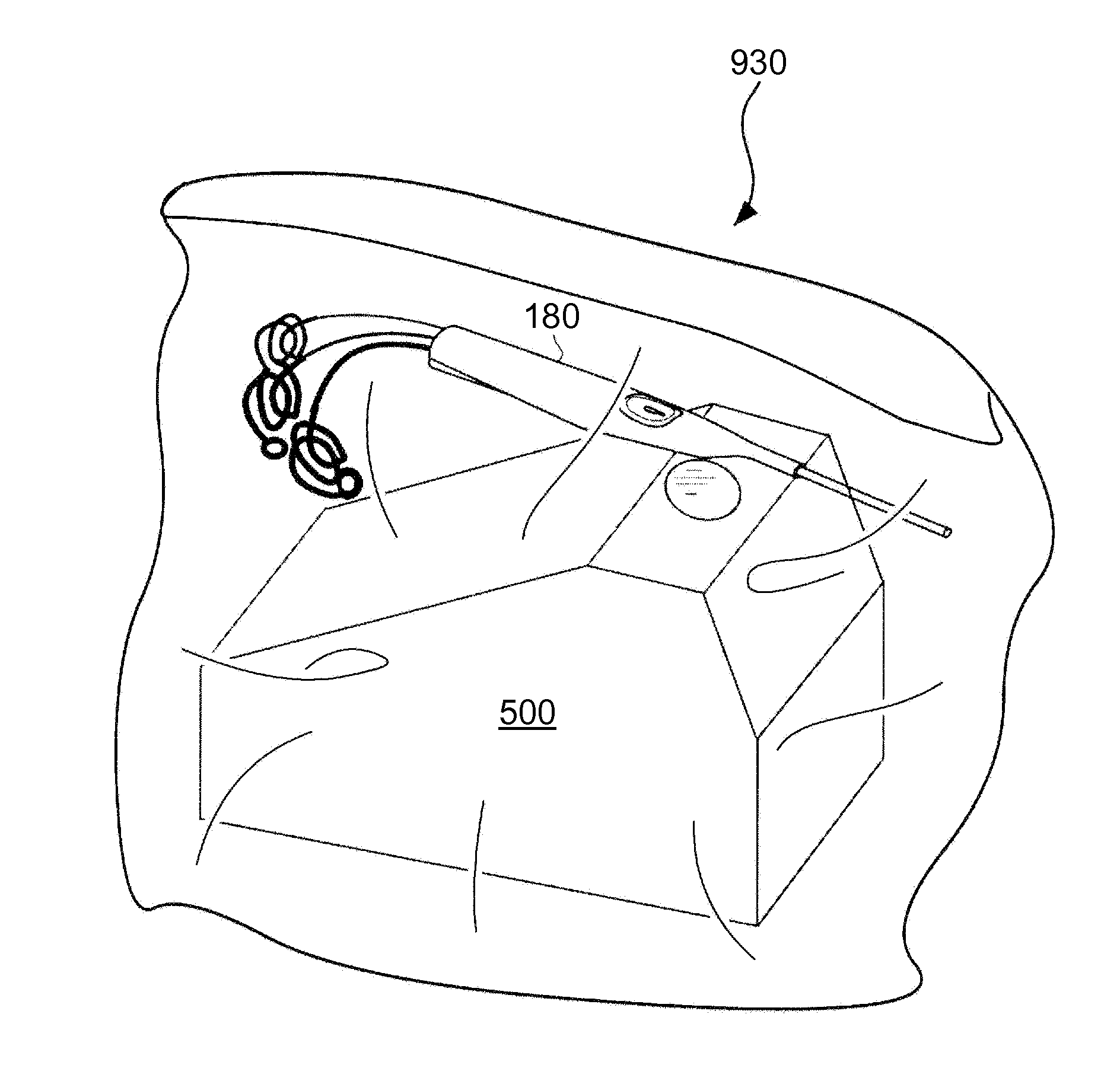
[0082]FIG. 7 is an explanatory view showing the state where a liquid ejection device 600 is installed on a stand 700 as the second embodiment. The illustrated stand 700 is provided with an ID display portion 730 to which an identification ID that is unique to each stand 700 is attached. In the liquid ejection device 600, a reading unit 610 which reads the identification ID is provided at the position corresponding to the ID display portion 730 of the stand 700 when the liquid ejection device 600 is set on the stand 700. Data read by the reading unit 610 is transmitted to the control unit 400 via the cable CBL.

[0083]In the stand 700 of the sec...

Example

3 Third Embodiment

[0085]Next, a third embodiment of the invention will be described. FIG. 8 shows the schematic configuration of a stand 800 as the third embodiment. The stand 800 of the third embodiment has a liquid storage section 820, as illustrated. This liquid storage section 820 is connected to a stand-side suction pump 826 via a discharge passage 822 and a first drainage tube 824. The stand-side suction pump 826 is connected to the drainage container 320 (see FIG. 2) in which the liquid sucked by the suction pump 300 on the side of the liquid ejection device 100 is housed, via a second drainage tube 828.

[0086]As the stand-side suction pump 826 is thus provided for the stand 800, the liquid that flows out to the liquid storage section 820 in the initial filling operation and the liquid discharge operation to discharge air bubbles can be sucked using the strand-side pump 826. Also, if the stand-side suction pump 826 is driven in the state where the liquid ejection device 100 is...


PUM


Abstract

A medical instrument holding apparatus (stand) that holds a medical instrument having a functional unit, includes: an instrument housing unit capable of housing at least a part of the instrument; and a coordination unit which coordinates with the functional unit when at least apart of the instrument is housed in the instrument housing unit. Thus, as the medical instrument is housed in this medical instrument holding apparatus, coordination between the two is possible.

Description

[0001]This application claims the benefit of Japanese Patent Application No. 2013-166012, filed on Aug. 9, 2013. The content of the aforementioned application is incorporated herein by reference in its entirety.BACKGROUND[0002]1. Technical Field[0003]The present invention relates to a medical instrument holding apparatus which holds a medical instrument having a functional unit inside.[0004]2. Related Art[0005]Recently, various medical instruments such as electric surgical knife are proposed. There is, for example, a liquid ejection device which ejects a liquid such as water or physiological saline solution in a pulse form from a nozzle to excise or incise a living tissue (JP-A-2008-82202). If this liquid ejection device is used for a surgical operation, the operation can be carried out without causing heat damage to the living tissue or damaging tissues of blood vessels, nerves and the like. Such a liquid ejection device has a medical instrument which the operator holds in the hand...

Claims


Application Information

Patent Timeline
IPC IPC(8): A61B19/02F16M11/22A61B19/00
CPCA61B19/02F16M11/22A61B19/34A61B17/3203A61B2017/00473A61B50/22A61B90/50A61B90/70A61B50/20A61B50/30A61B90/90
Inventor SEKINO, HIROKAZUHIRABAYASHI, ATSUYAKAWAKAMI, DAISUKE
Owner SEIKO EPSON CORP
Why Eureka
Try Eureka