Lighting solution for apparatuses for vacuum insulating glass (VIG) unit tip-off, and/or associated methods

a technology of vacuum insulation glass and apparatus, applied in the direction of laser beam welding apparatus, manufacturing tools, doors/windows, etc., can solve the problems of temperature uniformity issues within the oven body, complicated design, space between subsequent levels, etc., to facilitate the location of the pump-out tube and increase the contrast in the area.

Active Publication Date: 2013-06-20
GUARDIAN GLASS LLC
View PDF21 Cites 32 Cited by
  • Summary
  • Abstract
  • Description
  • Claims
  • Application Information

AI Technical Summary

Benefits of technology

[0010]Unfortunately, there are several drawbacks associated with the current approach shown in and described in connection with FIG. 3. The laser is enclosed in an insulated and cooled box to reduce the likelihood of damage to the laser source. This arrangement complicates the design and oftentimes plural individualized cooling subsystems. This arrangement also typically include access doors and / or panels that open to allow the laser to be inserted into the oven, removed when damaged, etc. Providing access to the laser, however, has been found to result in temperature uniformity issues within the body of the oven and on the surface VIG subassembly. To compensate for these non-uniformities, additional controls and heating capabilities are provided to reduce the non-uniformities. Another disadvantage relates to the space between subsequent levels, which is fairly large since each stage includes rollers, accommodates a VIG unit, and has an insulated and cooled box housing a laser. This increases vertical space requirements and / or restricts how many units can be stacked on top of one another.
[0017]In certain example embodiments, a laser tip-off system for a vacuum insulating glass (VIG) unit is provided. An oven has an oven interior and a sidewall in which at least one opening is formed, with at least one window being located in the at least one opening. At least one reflector is located in the oven interior. At least one laser source is located outside of the oven, with the at least one laser source being aligned with the window and configured to emit a laser beam towards the at least one reflector. The at least one reflector is oriented within the oven interior to cause laser beams emitted from the at least one laser source to be redirected towards a pump-out tube of a VIG unit subassembly provided to the oven interior. A vision system is configured to provide positional data for facilitating the melting of the pump-out tube. A lighting system is located remote from the oven. A quartz rod is configured to convey light from the lighting system to an area proximate the pump-out tube and through VIG unit so as to increase contrast in that area.
[0021]In certain example embodiments, a laser tip-off system for a vacuum insulating glass (VIG) unit is provided. The system includes an oven; at least one laser source for melting a pump-out tube of the VIG unit; a vision system configured to provide positional data for facilitating the melting of the pump-out tube; a backlighting system located remote from the oven; and a quartz rod configured to convey light from the lighting system to an area proximate the pump-out tube and through VIG unit so as to increase contrast in that area and facilitate location of the pump-out tube by the vision system.

Problems solved by technology

Unfortunately, there are several drawbacks associated with the current approach shown in and described in connection with FIG. 3.
This arrangement complicates the design and oftentimes plural individualized cooling subsystems.
Providing access to the laser, however, has been found to result in temperature uniformity issues within the body of the oven and on the surface VIG subassembly.
Another disadvantage relates to the space between subsequent levels, which is fairly large since each stage includes rollers, accommodates a VIG unit, and has an insulated and cooled box housing a laser.
This increases vertical space requirements and / or restricts how many units can be stacked on top of one another.

Method used


Image

  • Lighting solution for apparatuses for vacuum insulating glass (VIG) unit tip-off, and/or associated methods
  • Lighting solution for apparatuses for vacuum insulating glass (VIG) unit tip-off, and/or associated methods
  • Lighting solution for apparatuses for vacuum insulating glass (VIG) unit tip-off, and/or associated methods

Examples


Embodiment Construction

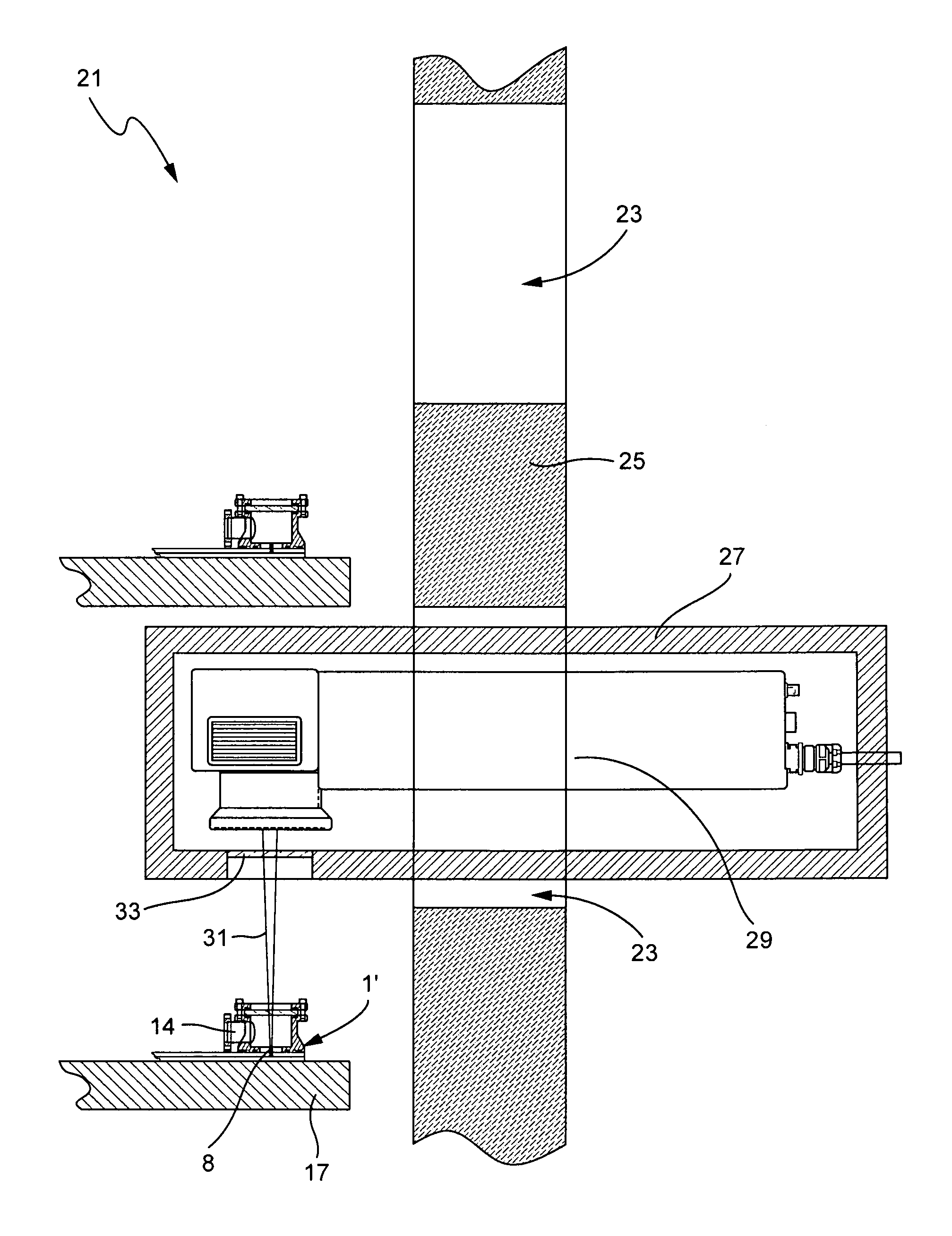
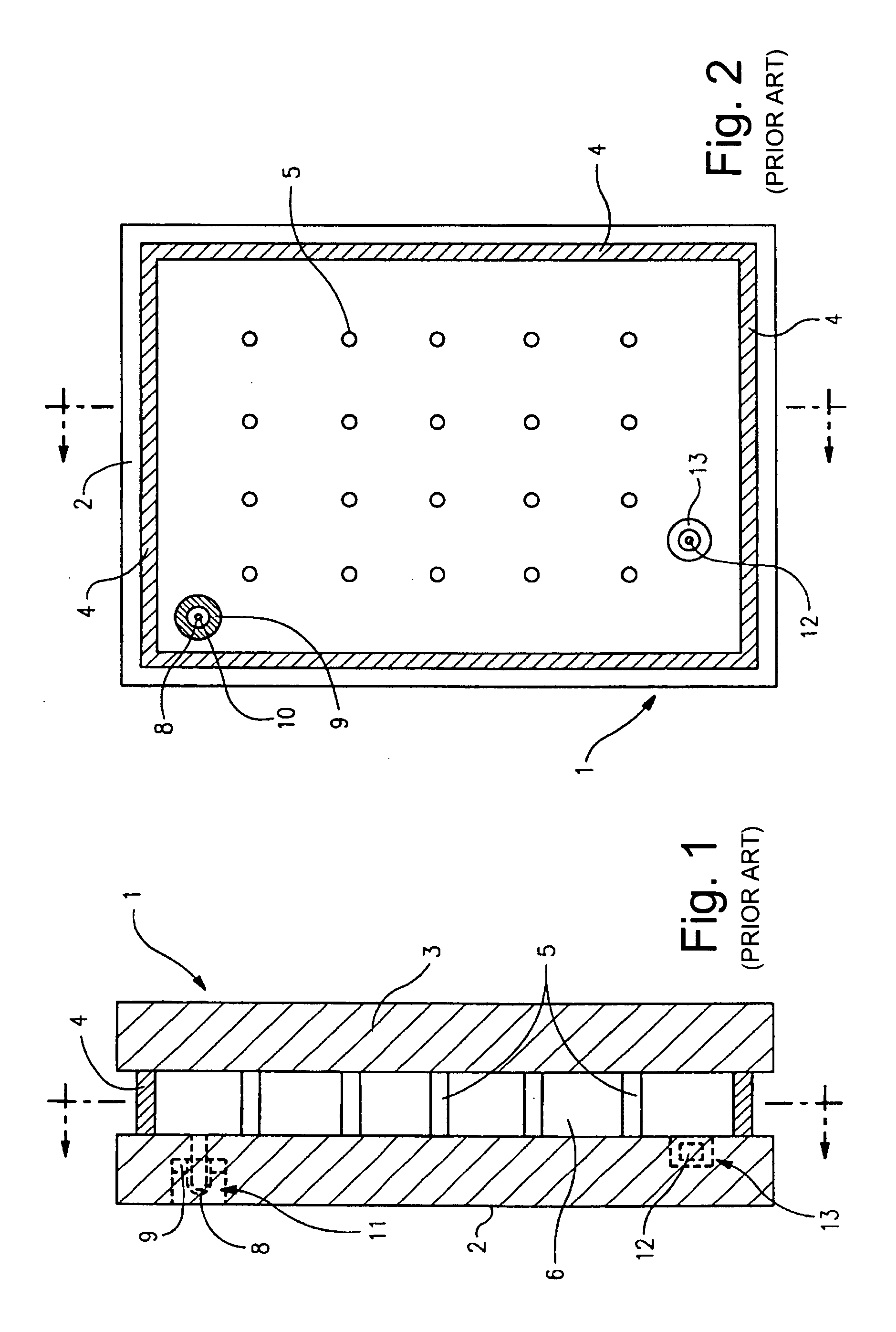
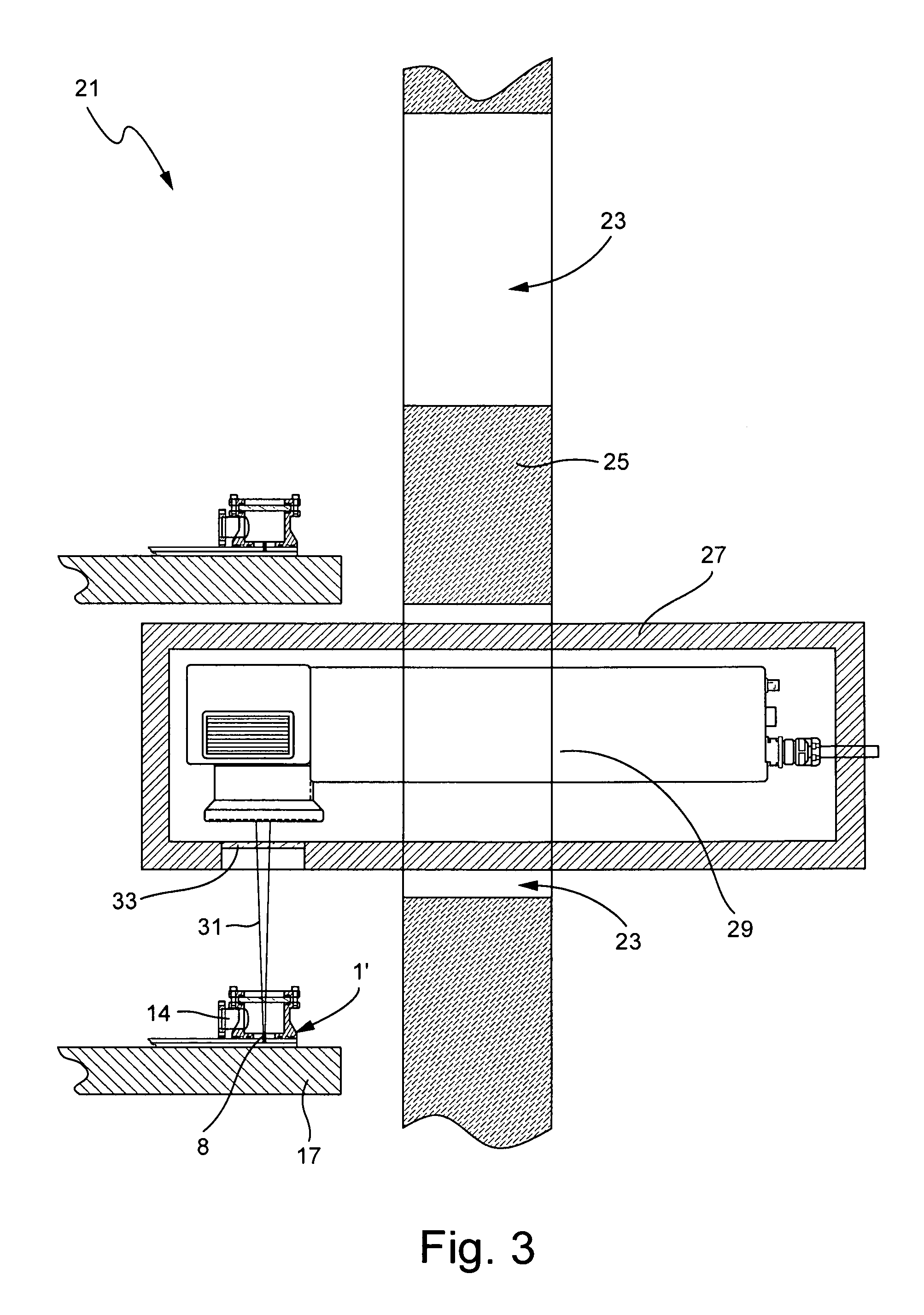
[0033]Certain embodiments of this invention relate to an improved peripheral or edge seal in a vacuum IG window unit, and / or a method of making the same. “Peripheral” and “edge” seals herein do not mean that the seals are located at the absolute periphery or edge of the unit, but instead mean that the seal is at least partially located at or near (e.g., within about two inches) an edge of at least one substrate of the unit. Likewise, “edge” as used herein is not limited to the absolute edge of a glass substrate but also may include an area at or near (e.g., within about two inches) of an absolute edge of the substrate(s). Also, it will be appreciated that as used herein the term “VIG assembly” refers to an intermediate product prior to the VIG's edges being sealed and evacuation of the recess including, for example, two parallel-spaced apart substrates and a frit. Also, while the frit may be said to be “on” or “supported” by one or more of the substrates herein, this does not mean t...


PUM

PropertyMeasurementUnit
temperatureaaaaaaaaaa
atmospheric pressureaaaaaaaaaa

Abstract

Certain example embodiments of this invention relate to apparatuses for sealing the tips of pump-out tubes of vacuum insulating glass (VIG) units, and / or associated methods. In certain example embodiments, a laser source used in sealing the pump-out tube is thermally insulated from the VIG unit and emits a laser beam through one or more windows in an oven towards a mirror located therein. The mirror is located so as to redirect the laser beam onto the pump-out tube to thereby seal it. For instance, a substantially horizontal laser beam emitted from a laser source located outside the oven enters into the oven through one or more windows and is reflected by a mirror towards the pump-out tube to be sealed. The repositioning of the laser source advantageously can change its effective focal length and / or the location of the laser beam, e.g., because of the fixed location of the mirror.

Description

FIELD OF THE INVENTION[0001]Certain example embodiments of this invention relate to apparatuses and / or methods used in making vacuum insulating glass (VIG) units. More particularly, certain example embodiments relate to apparatuses for sealing the tips of pump-out tubes, and / or associated methods. In certain example embodiments, a laser source used in sealing the pump-out tube is thermally insulated from the VIG unit and emits a laser beam through a window in an oven towards a mirror located therein, the mirror being located so as to redirect the laser beam onto the pump-out tube to thereby seal it.BACKGROUND AND SUMMARY OF EXAMPLE EMBODIMENTS OF THE INVENTION[0002]Vacuum IG units are known in the art. For example, see U.S. Pat. Nos. 5,664,395, 5,657,607, and 5,902,652, the disclosures of which are all hereby incorporated herein by reference.[0003]FIGS. 1-2 illustrate a conventional vacuum IG unit (vacuum IG unit or VIG unit). Vacuum IG unit 1 includes two spaced apart glass substra...

Claims


Application Information

Patent Timeline
Patent Type & Authority Applications(United States)
IPC IPC(8): B23K26/00
CPCE06B3/6612Y02B80/24E06B3/6675Y02A30/249Y02B80/22
Inventor DEAR, RYAN L.
Owner GUARDIAN GLASS LLC
Why Eureka
Try Eureka