Split-ring gland pipe coupling with corrugated armor and annular gasket having pressure assist slot

a technology of annular gaskets and corrugated armor, which is applied in the direction of hose connections, manufacturing tools, mechanical equipment, etc., can solve the problems of affecting so as to improve reduce the cost. , the effect of improving the quality of pipe couplings

Active Publication Date: 2013-08-01
SENSUS SPECTRUM LLC
View PDF3 Cites 21 Cited by
  • Summary
  • Abstract
  • Description
  • Claims
  • Application Information

AI Technical Summary

Benefits of technology

[0007]The present invention in one aspect includes an improved annular gasket that provides the advantages of vent holes but without their drawbacks. To that end, and in accordance with certain principles of the present invention, the inner side surface of the gasket is provided with one or more cross grooves in the form of indentations adjacent to and extending into the opening of the pressure assist slot at the inner side surface. Each of the cross grooves defines a radially extending pathway from the slot opening along the inner side surface, but is recessed beyond the inner side surface so as to provide a fluid communication path into the interior portion of the pressure assist slot even if the opening of the pressure assist slot is clamped shut by compression of the gasket with a split-ring gland. The cross grooves can be formed when the gasket is molded by the same structure used to form the pressure assist slot, making the manufacturing process easier, more reliable, and less costly than inclusion of separate vent holes. Moreover, because the cross grooves extend immediately from the opening, there is less risk that they might become blocked by the rest of the structure of the pipe coupling as might occur with the vent holes.

Problems solved by technology

Also, during installation with conventional armors, the gasket would tend to “bunch up” at the ends of the armor, making it difficult to properly install the pipe coupling.
But the lubrication further hampers installation as the components are more difficult to handle and can hold dirt and other debris to the parts which is undesirable.
Moreover, bunching was not always avoided even with lubrication.

Method used


Image

  • Split-ring gland pipe coupling with corrugated armor and annular gasket having pressure assist slot
  • Split-ring gland pipe coupling with corrugated armor and annular gasket having pressure assist slot
  • Split-ring gland pipe coupling with corrugated armor and annular gasket having pressure assist slot

Examples


Embodiment Construction

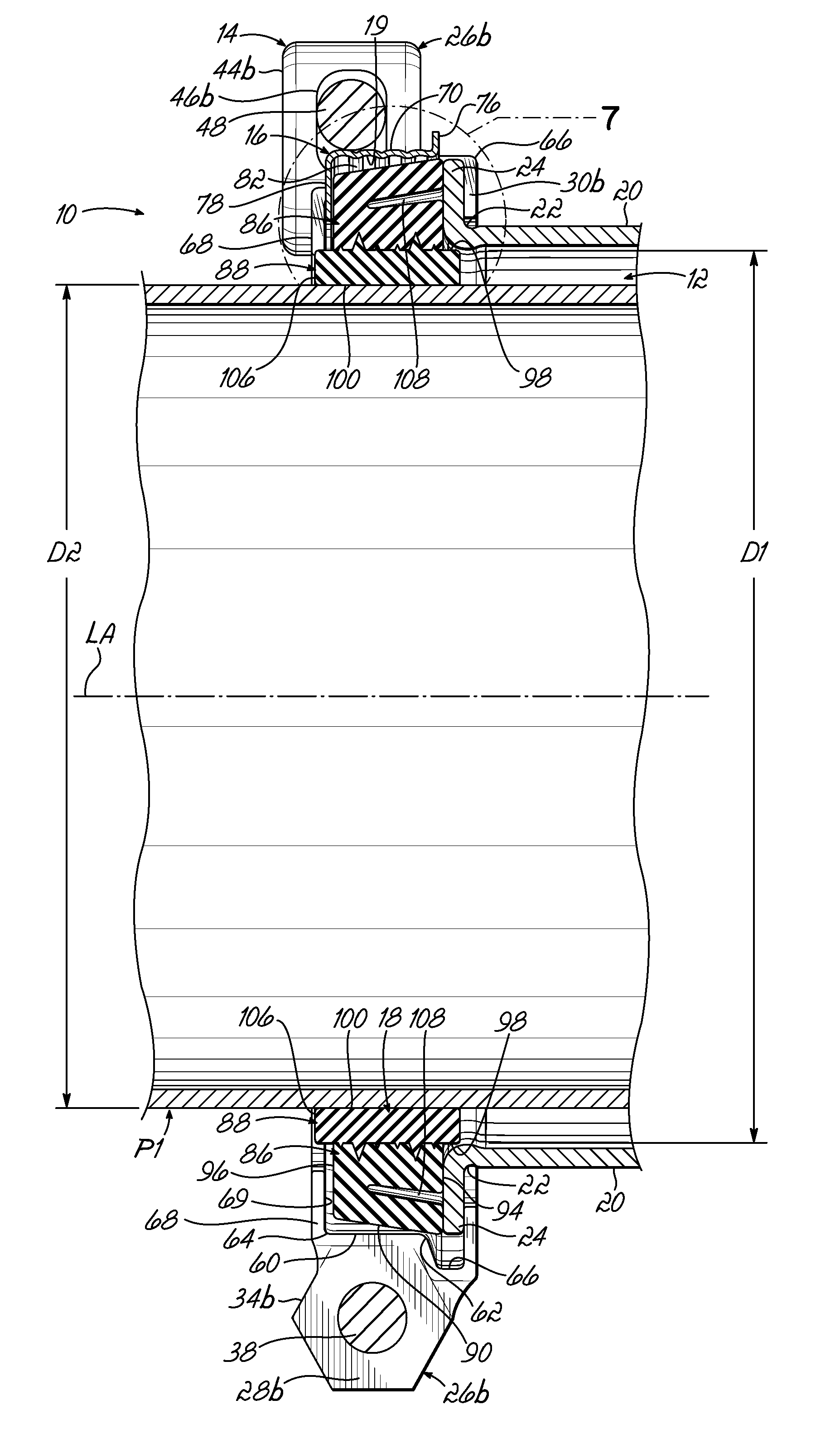
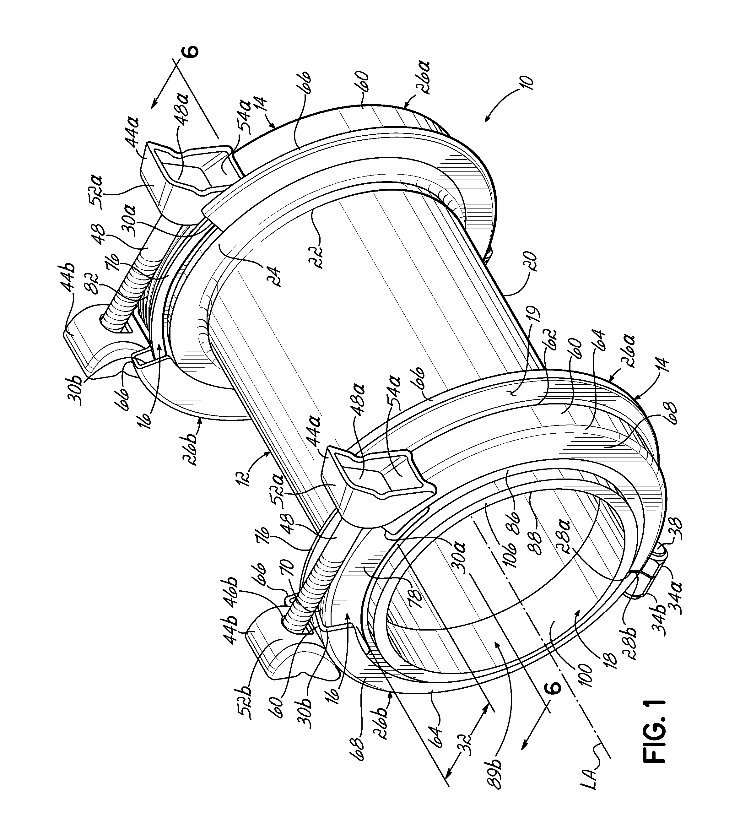
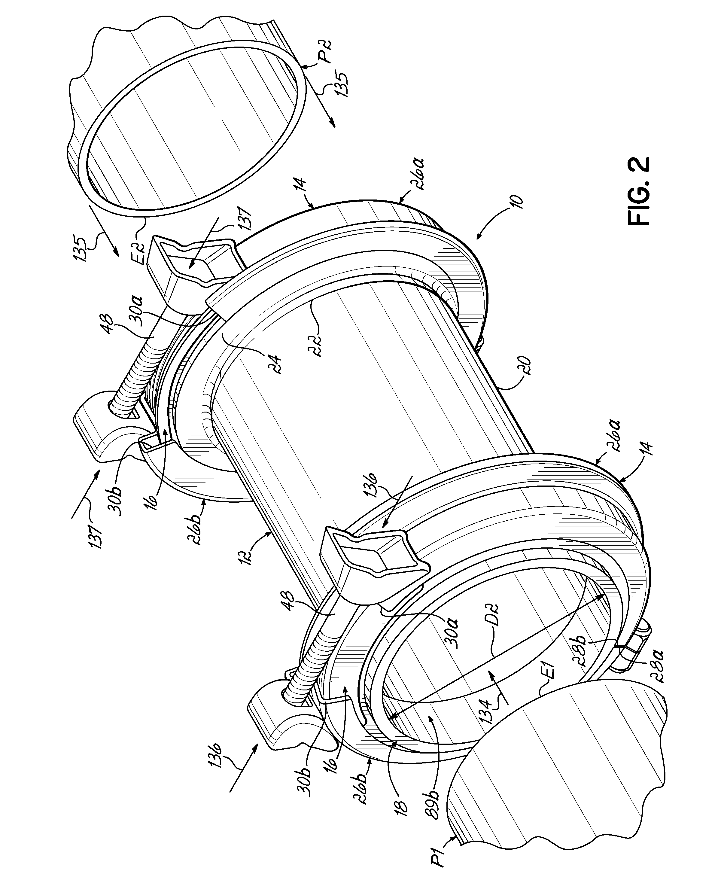
[0030]With reference to FIGS. 1 and 2, a split-ring gland type of pipe coupling 10 according to one embodiment of the present invention is shown. The pipe coupling 10 includes a sleeve 12, a pair of split-ring glands 14, a bridge plate or armor 16 associated with each split-ring gland 14, and an annular gasket 18 associated with each split-ring gland 14. In the fully assembled state of the pipe coupling 10, an end E1 of a first pipe P1 is inserted into the sleeve 12 through one of the split-ring glands 14 and the corresponding gasket 18, and an end E2 of a second pipe P2 is inserted into the other split-ring gland 14 and associated gasket 18. The split-ring glands 14 are configured to be tightened onto the corresponding gaskets 18 to compress the gaskets 18 into sealing connection with the respective pipe ends E1, E2. The split-ring gland 14 and the armor 16 collectively define a generally closed annular periphery 19 around the gasket 18, which further ensures that fluid passing thr...


PUM

PropertyMeasurementUnit
diameteraaaaaaaaaa
diameteraaaaaaaaaa
diameteraaaaaaaaaa

Abstract

A pipe coupling for coupling adjacent ends of a pair of pipes includes a sleeve, a split-ring gland positioned around one of the ends of the sleeve, and an annular gasket positioned within the split-ring gland and configured to be compressed by the split-ring gland for sealing one pipe end to the sleeve. The split-ring gland includes two partially circular gland members with spaced ends defining a gap, which is spanned by an armor positioned in the gap to provide a generally closed annular periphery about the gasket. The armor includes a corrugated portion engaging the gasket during compression. The gasket includes a pressure assist slot configured to receive pressurized fluid leaking from the pipes and a plurality of cross grooves ensuring continued fluid communication with the pressure assist slot. The gasket also includes ribs engaging the split-ring gland and the armor to reduce or eliminate added lubrication necessary.

Description

FIELD OF THE INVENTION[0001]The present invention relates generally to pipe couplings and joints and, more particularly, to pipe couplings adapted to couple and seal adjacent ends of two pipe sections of the same or different diameters.BACKGROUND OF THE INVENTION[0002]Conventional pipe couplings for coupling and sealing adjacent ends of two pipe sections include a coupling sleeve or collar with each pipe end extending into a respective end of the coupling sleeve. A gasket is held adjacent each end of the sleeve overlying the pipe section. An annular flange or gland is associated with each gasket and end of the sleeve, and is tightened to draw down the gasket against the pipe end thus sealing the pipe coupling thereto. One pipe coupling is shown in my prior U.S. Pat. No. 6,168,210 and utilizes continuous flanges that are coupled together via bolts spanning the sleeve. The flanges, sleeve ends, and gaskets have particular relationships that affect the seal and allow the coupling to wo...

Claims


Application Information

Patent Timeline
Patent Type & Authority Applications(United States)
IPC IPC(8): F16L19/00B23P11/00
CPCF16L21/04Y10T29/49826F16L25/14F16L21/022
Inventor BIRD, EDWIN A.MOSS, TRAVIS SCOTT
Owner SENSUS SPECTRUM LLC
Why Eureka
Try Eureka