High Voltage Testing Device and High Voltage Testing Method Thereof

a high-voltage testing and high-voltage technology, applied in the direction of line-transmission monitoring/testing, line-transmission details, instruments, etc., can solve the problems of variable problems, capacitors of coaxial cables may be possibly broken by applying excessive high-voltage, etc., and achieve the effect of simple operation

Inactive Publication Date: 2013-09-19
YAZAKI CORP
View PDF16 Cites 9 Cited by
  • Summary
  • Abstract
  • Description
  • Claims
  • Application Information

AI Technical Summary

Benefits of technology

[0012]The present invention is devised by considering the above-described circumstances, and it is an object of the present invention to provide a high voltage testing device which can carry out a test of an entire part of a cable by a simple operation without breaking a capacitor even when a coaxial cable having a capacitor built therein is tested.
[0014]According to the high voltage testing device having the structure of the above-described (1), even when a capacitor is provided in the coaxial cable as the object to be inspected, the high voltage can be prevented from being applied between terminals of the capacitor. Further, the voltage for a test is applied to both the ends of the coaxial cable at the same time through the core wire short-circuiting part. Accordingly, an entire part of the coaxial cable can be tested by the test of one time without carrying out the tests individually two times. Even when the length of the coaxial cable as the object to be inspected is relatively large, the voltage applied between the terminals of the capacitor can be restrained from increasing.
[0015]According to the high voltage testing device having the structure of the above-described (2), a change speed of the high voltage applied to the coaxial cable as the object to be inspected from the tester can be moderated. Thus, an influence of an inductor component in the coaxial cable is mitigated. Accordingly, even when the length of the coaxial cable as the object to be inspected is relatively large, the voltage applied between the terminals of the capacitor can be restrained from increasing.
[0017]According to the high voltage testing device having the structure of the above-described (4), when both the ends of the coaxial cable as the object to be inspected are merely connected to the two coaxial connectors of the cable connecting part, the test can be safely carried out. Namely, an excessively high voltage can be prevented from being applied to the capacitor in the coaxial cable by a mal-operation.

Problems solved by technology

However, as described above, when the coaxial cable having the capacitor inserted into a part of the center conductor is tested, various problems may possibly arise.
Accordingly, when an operator makes an erroneous connecting operation during the test or when there is a problem in an insulation property of the coaxial cable itself, the capacitor of the coaxial cable may be possibly broken by applying an excessively high voltage.

Method used


Image

  • High Voltage Testing Device and High Voltage Testing Method Thereof
  • High Voltage Testing Device and High Voltage Testing Method Thereof
  • High Voltage Testing Device and High Voltage Testing Method Thereof

Examples


Embodiment Construction

[0030]Now, a specific exemplary embodiment of a high voltage testing device of the present invention will be described below by referring to the drawings.

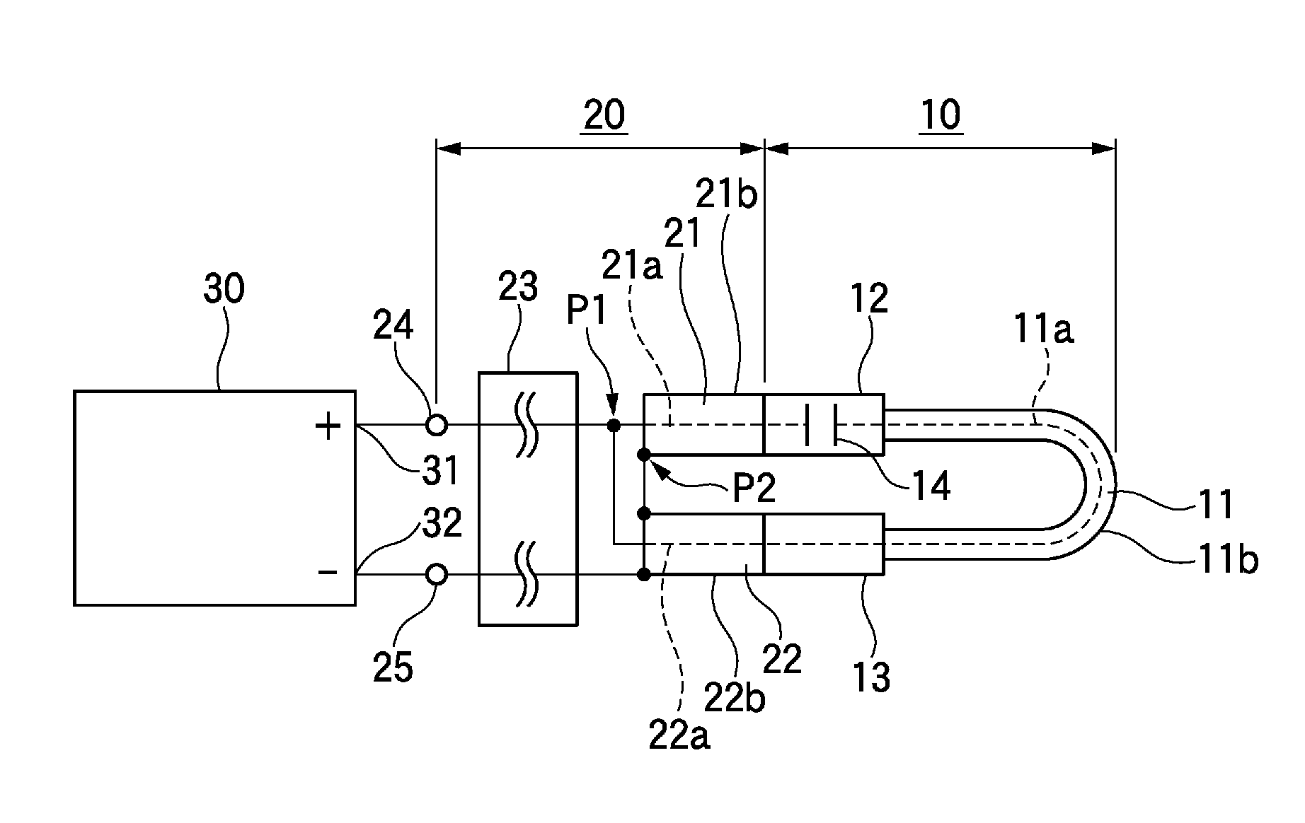
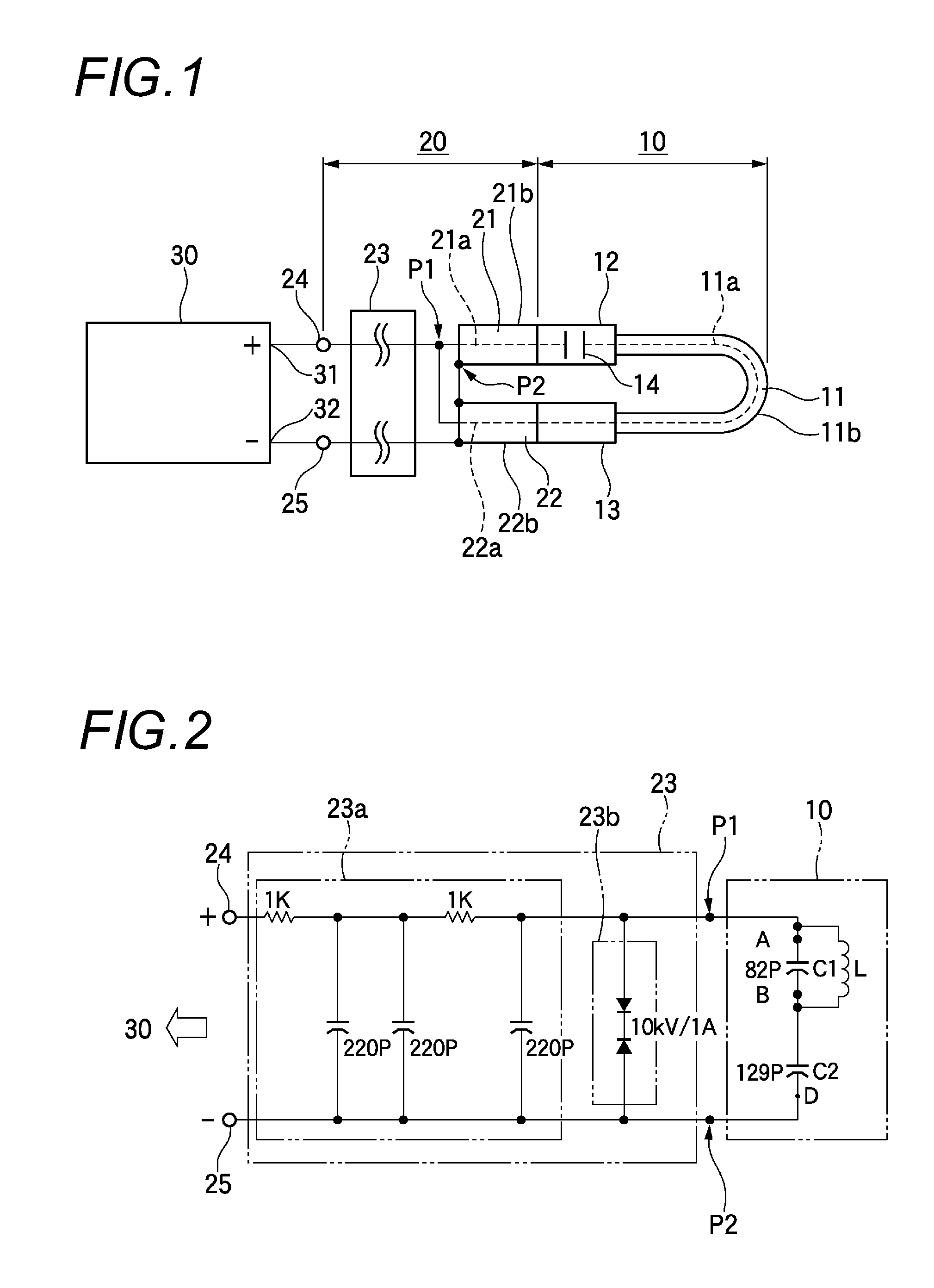
[0031]FIG. 1 shows a specific example of a connection state when a wire harness for an antenna is tested by using a high voltage testing device of an exemplary embodiment. Further, in the present exemplary embodiment, as a representative example, a wire harness 10 for an antenna as shown in FIG. 3 is supposed to be used as an object to be inspected.

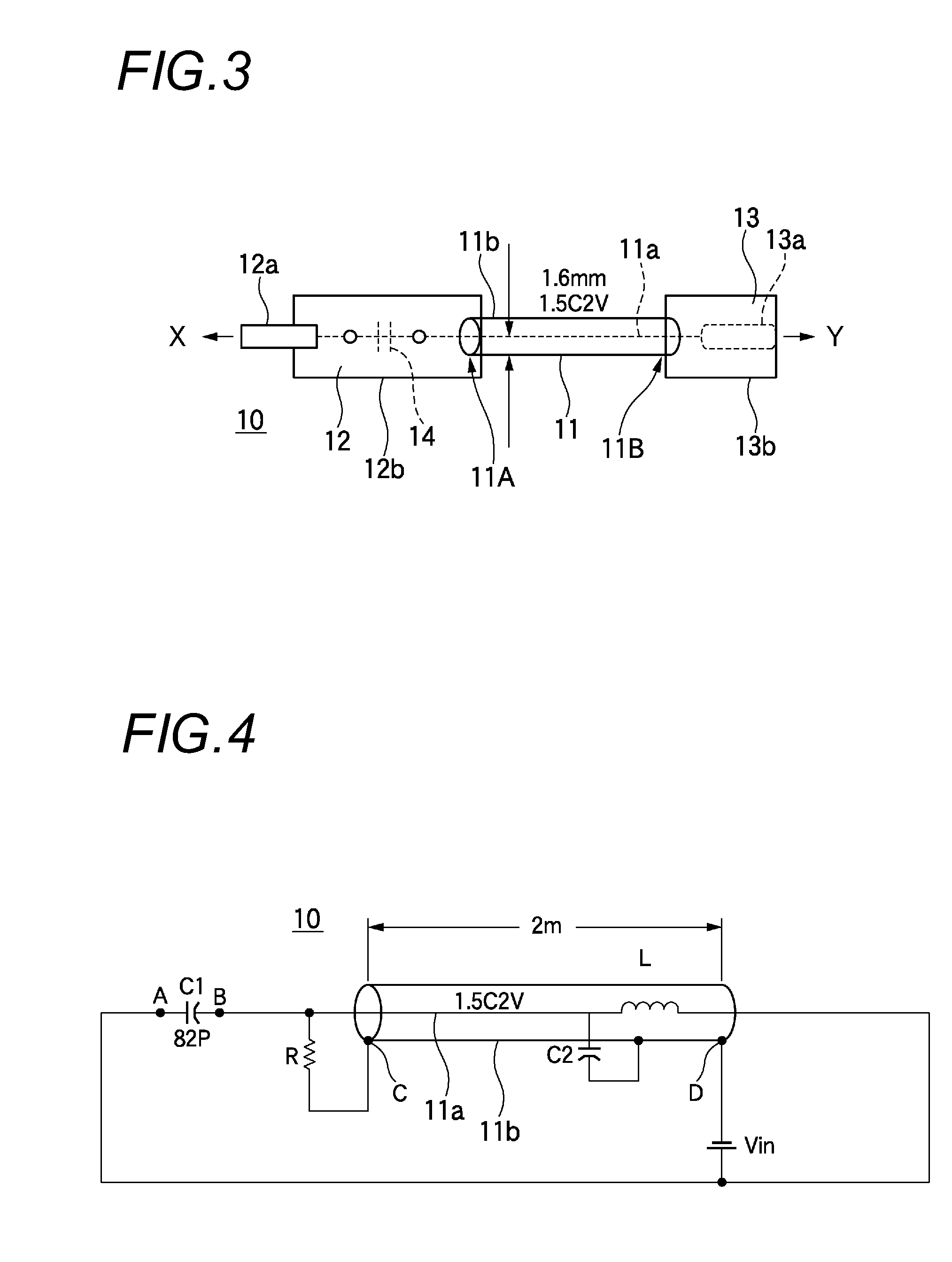
[0032]The wire harness 10 for an antenna is used, as shown in FIG. 3, to connect a prescribed radio unit (an input of a broadcasting radio receiver mounted on a vehicle) X to an antenna amplifier (an amplifier which amplifies a high frequency signal from an antenna mounted on a vehicle) Y. Further, as shown in FIG. 3, the wire harness 10 for the antenna includes a coaxial cable (1.5C2V) 11 having a length to some degree (for instance, 1.6 m) and harness side connectors 12 and 13 respecti...


PUM


Abstract

A high voltage testing device for testing a coaxial cable including a central conductor and a shield conductor surround a periphery of the central conductor with an insulating material and applying a high voltage between the central conductor and the shield conductor of the coaxial cable, includes a cable connecting part that respectively connects two electrodes of an output of a tester which outputs a high voltage to the central conductor and the shield conductor of the coaxial cable. The cable connecting part includes a core wire short-circuiting part which electrically short-circuits between one end and the other end in the longitudinal direction of the central conductor of the coaxial cable and a shield wire short-circuiting part which electrically short-circuits between one end and the other end in the longitudinal direction of the shield conductor of the coaxial cable.

Description

CROSS REFERENCE TO RELATED APPLICATIONS[0001]This application is a continuation of PCT application No. PCT / JP2011 / 075303, which was filed on Nov. 2, 2011 based on Japanese Patent Application (No. 2010-246474) filed on Nov. 2, 2010, the contents of which are incorporated herein by reference.BACKGROUND OF THE INVENTION[0002]1. Field of the Invention[0003]The present invention relates to a high voltage testing device which uses a coaxial cable as an object to be inspected and applies a high voltage between a center conductor (a core wire) and a shield conductor of the coaxial cable to carry out a test of an electric insulation state and a high voltage testing method of the high voltage testing device.[0004]2. Description of the Related Art[0005]For instance, when an input of a radio device such as a radio or a television is connected to an antenna, a coaxial cable is ordinarily used. Such kind of coaxial cable is formed with a center conductor having a prescribed thickness and a shield...

Claims


Application Information

Patent Timeline
Patent Type & Authority Applications(United States)
IPC IPC(8): G01R31/02
CPCG01R31/021G01R31/1272G01R31/58
Inventor OIWA, KAZUYUKIYAGI, DAISUKE
Owner YAZAKI CORP
Why Eureka
Try Eureka