State Control System and State Control Method

a state control system and state control technology, applied in the field of state control systems, can solve the problems of increasing the size of the portable terminal, the inability of the portable terminal to save its power consumption, and the power consumption of the portable terminal. to achieve the effect of maintaining the security level and saving the power consumption of the portable terminal

Inactive Publication Date: 2013-10-17
HITACHI LTD
View PDF8 Cites 38 Cited by
  • Summary
  • Abstract
  • Description
  • Claims
  • Application Information

AI Technical Summary

Benefits of technology

[0010]In view of the above, this invention aims to provide a state control system that can save the power consumption of the portable terminal while maintaining the security level.
[0012]A brief description is now given of effects provided by the exemplary embodiment of this invention disclosed in this application. This invention enables to provide a state control system that can save the power consumption of the portable terminal while maintaining the security level.

Problems solved by technology

If a portable terminal frequently sends such signals to unlock the controlled object, the portable terminal consumes more power.
The increase in size of the battery or the receiving antenna causes increase in size of the portable terminal.
In the room access control system according to JP 2007-107194 A, an ID tag sends a signal to unlock the door if the user is positioned close to the door; consequently, the portable terminal cannot save its power consumption.

Method used


Image

  • State Control System and State Control Method
  • State Control System and State Control Method
  • State Control System and State Control Method

Examples


first embodiment

[0032]A first embodiment of this invention is described using FIGS. 1 to 11.

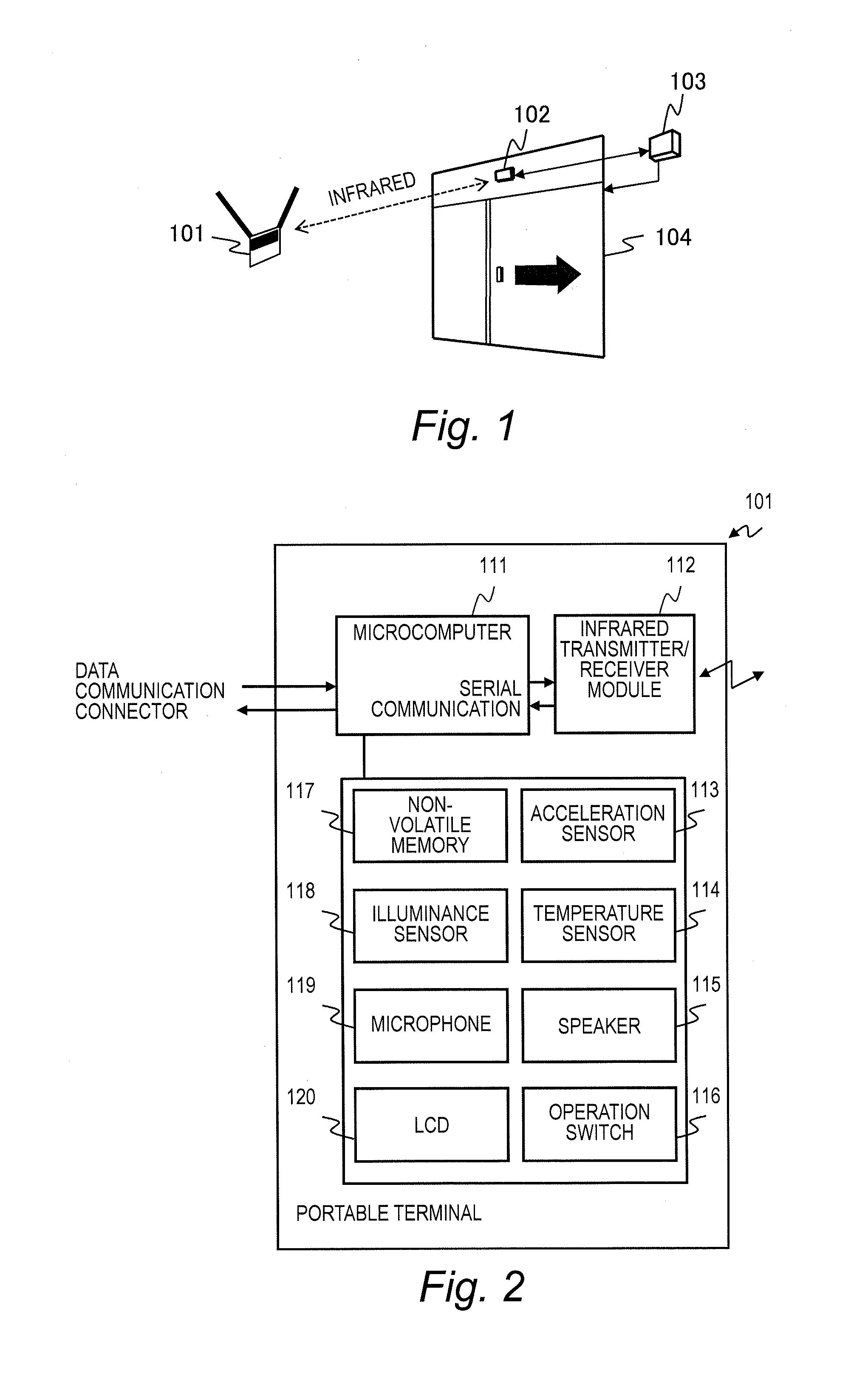
[0033]FIG. 1 is an explanatory diagram illustrating a configuration of a room access control system in the first embodiment.

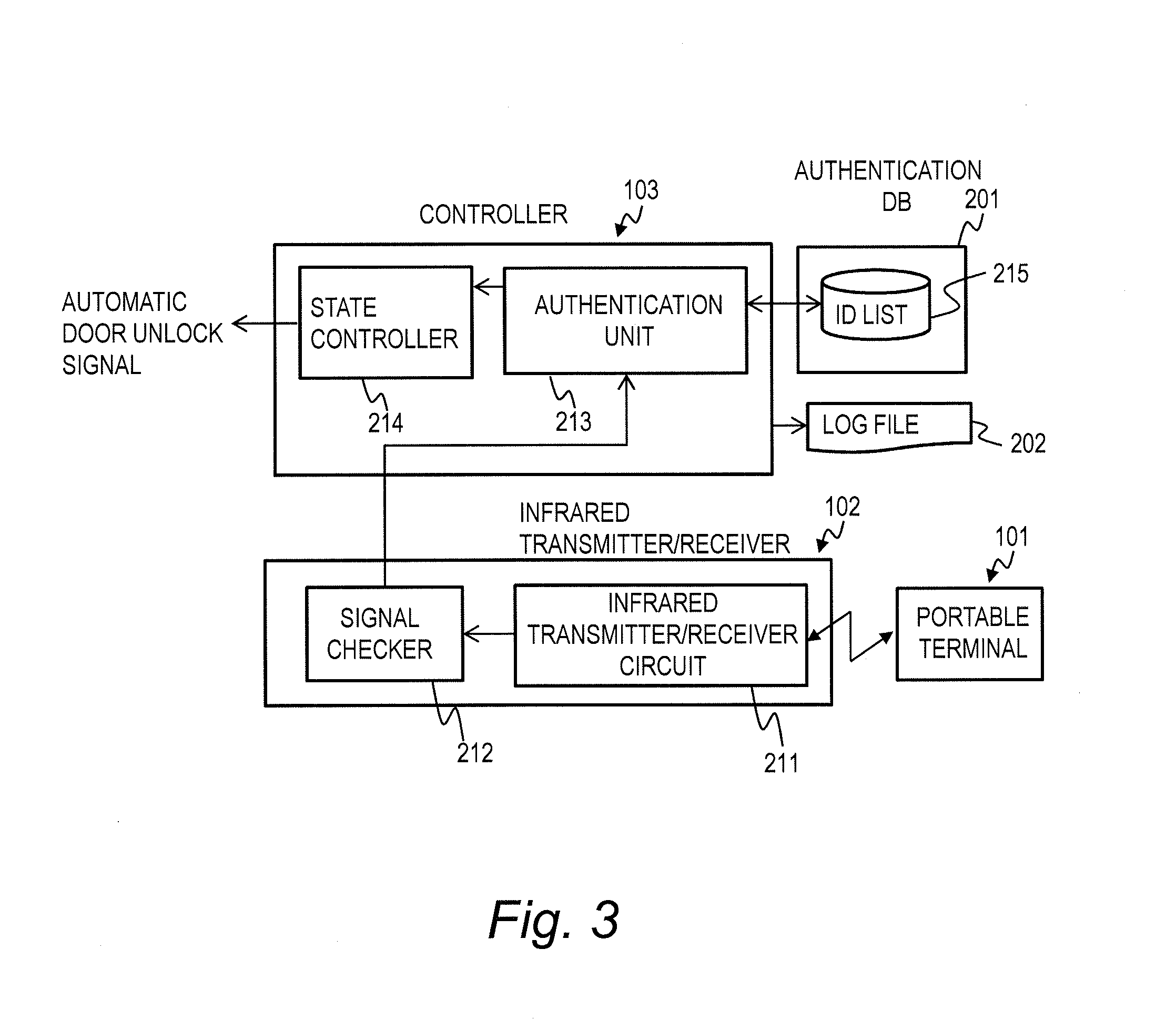
[0034]The room access control system includes a portable terminal 101 held by a user, an infrared transmitter / receiver 102, a controller (control apparatus) 103, and an automatic door (controlled object) 104.

[0035]The portable terminal 101 sends a signal including identification information to an external via infrared and receives an infrared signal from the external. The infrared transmitter / receiver 102 sends the signal sent from the portable terminal 101 to the controller 103 and sends a request for a signal to the portable terminal 101.

[0036]The controller 103 authenticates the signal sent from the portable terminal 101 and controls the state of the automatic door 104, whether or not to lock the automatic door 104, based on the signal sent from the portable terminal 101. The automat...

second embodiment

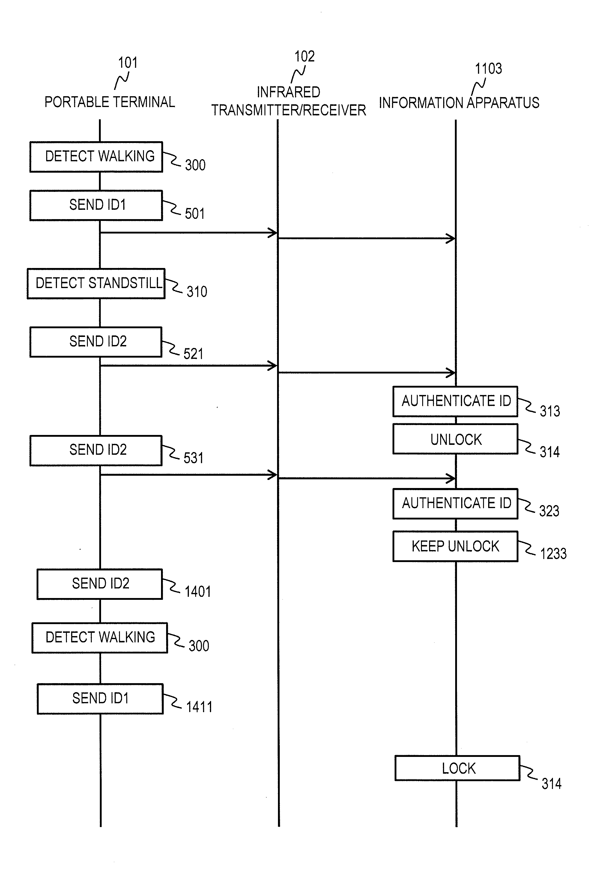
[0145]A second embodiment of this invention is described using FIGS. 12 to 15.

[0146]The first embodiment has described a room access control system in which the controller 103 controls the state of the automatic door 104; this embodiment describes a state control system for information apparatus in which a controller 103 controls the state of an information apparatus 1103 (refer to FIG. 12).

[0147]FIG. 12 is a configuration diagram of the state control system for information apparatus in the second embodiment.

[0148]The state control system for information apparatus includes a portable terminal 101, an infrared transmitter / receiver 102, an information apparatus 1103, a display 1104 of an output device, a keyboard 1105 of an input device, and a mouse 1106 of an input device. In the components shown in FIG. 12, the same components as those shown in FIG. 1 in the first embodiment are assigned the same reference signs and explanations thereof are omitted.

[0149]The functions of the control...


PUM


Abstract

A state control system comprises a portable terminal and a control apparatus. The portable terminal sends a signal including identification information to an external. The control apparatus controls a controlled object in either one of a locked state and an unlocked state based on the signal sent from the portable terminal. The portable terminal sends a first signal, in a case where a event detector has not detected the event, and sends a second signal having a data length longer than a data length of the first signal, in a case where the event detector has detected the event. The control apparatus controls a controlled object to the unlocked state in a case where the controlled object is in the locked state and the controlled apparatus receives the second signal.

Description

CLAIM OF PRIORITY[0001]The present application claims priority from Japanese patent application JP 2012-90243 filed on Apr. 11, 2012, the content of which is hereby incorporated by reference into this application.BACKGROUND OF THE INVENTION[0002]This invention relates to a state control system for controlling an object to be in a locked state or an unlocked state, and in particular, relates to a state control system for controlling the object to be in a locked state or an unlocked state based on a signal sent by a portable terminal.[0003]As information becomes more sophisticated, information security problems are becoming more serious; it is particularly desired to improve the security in accessing a room or an information apparatus.[0004]For a security system for controlling access to a room, there is a known system that unlocks a room door upon successful authentication with an ID card waved over a card reader for the room. For a security system for controlling access to an inform...

Claims


Application Information

Patent Timeline
Patent Type & Authority Applications(United States)
IPC IPC(8): G08C23/04
CPCG08C23/04
Inventor OHKUBO, NORIOWAKISAKA, YOSHIHIROHAYAKAWA, MIKI
Owner HITACHI LTD
Why Eureka
Try Eureka