Visual dynamic monitoring system for operating states of protective relay system

a dynamic monitoring and operating state technology, applied in the field of power systems, can solve the problems of improper operation of protective relays, inconvenience in behavior analysis of relays, etc., and achieve the effects of improving the reliability of the power system, avoiding the expansion of a power system disturbance, and improving the reliability of the protective relay system

Inactive Publication Date: 2013-10-24
SHANGHAI YIHAO AUTOMATION CO LTD
View PDF4 Cites 8 Cited by
  • Summary
  • Abstract
  • Description
  • Claims
  • Application Information

AI Technical Summary

Benefits of technology

[0021]What can be seen from the technical solution mentioned above is as follows. Under normal operation of the protective relay system, the visual dynamic monitoring method for operating states of the protective relay system according to a preferred embodiment of the present invention is capable of showing the operating states of the protective relay system, which accord with the protection principle designed and have a time sequential characteristic. Thus, technicians are capable of visually observing whether each component involved in the protective relay syste

Problems solved by technology

From practical point of view, the computer-based relay causes some inconvenience for the behavior analysis of relays in

Method used


Image

  • Visual dynamic monitoring system for operating states of protective relay system
  • Visual dynamic monitoring system for operating states of protective relay system
  • Visual dynamic monitoring system for operating states of protective relay system

Examples


embodiment 1

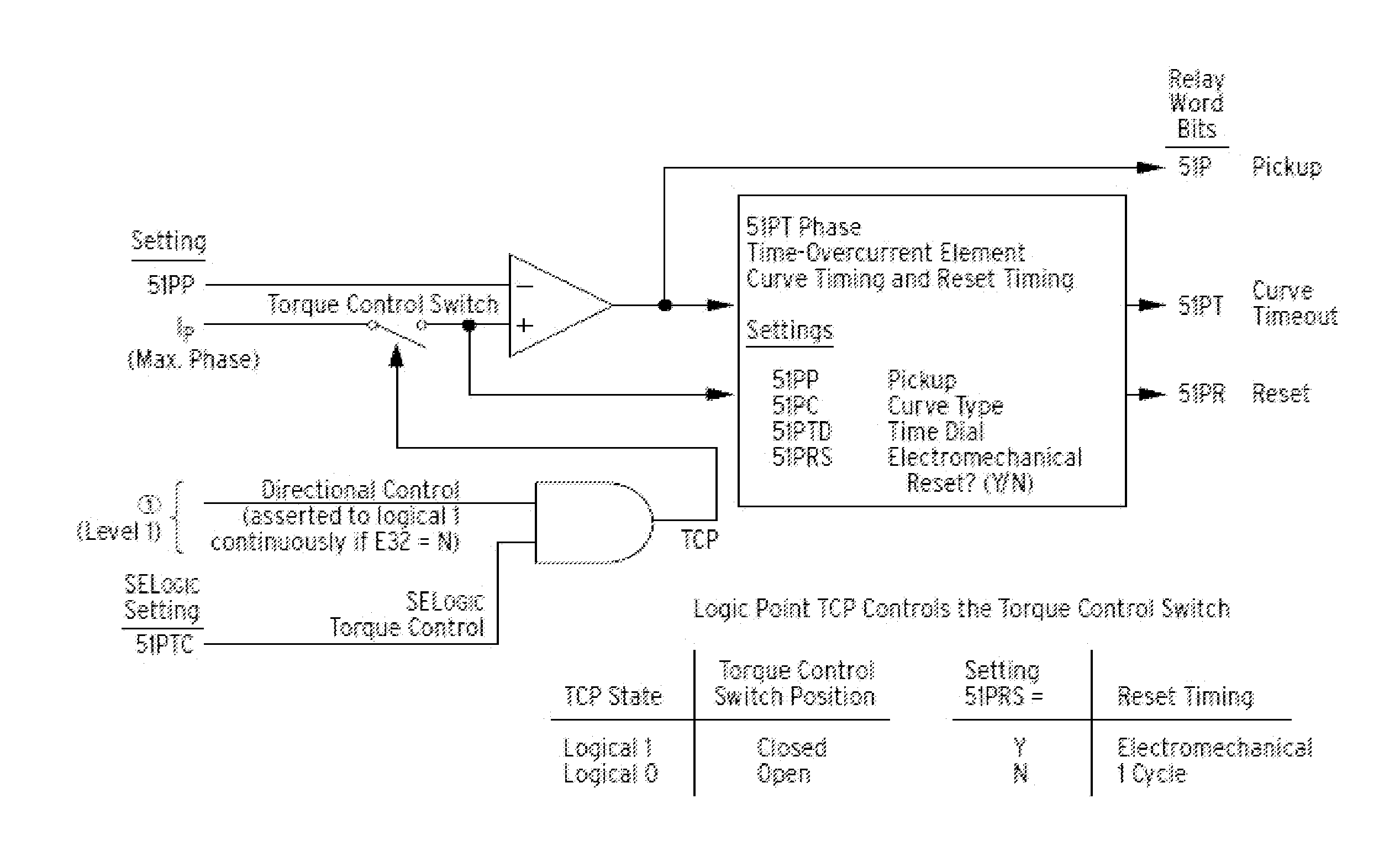
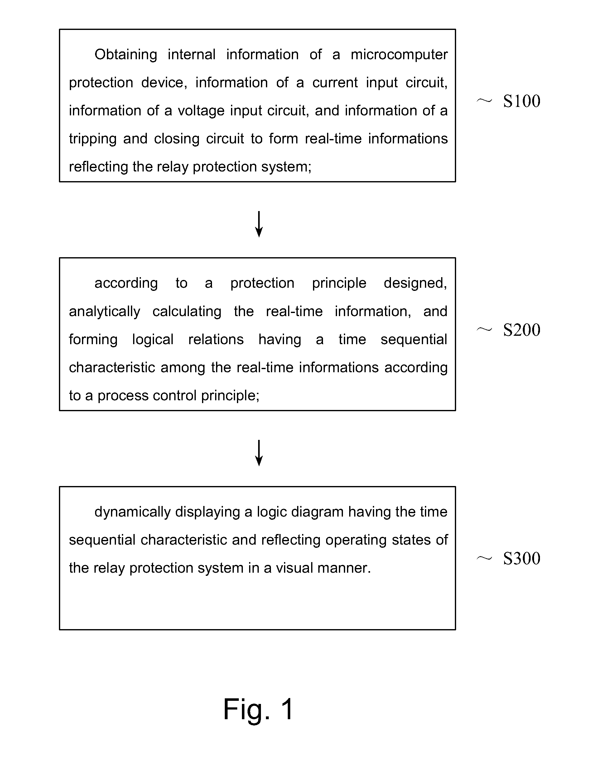
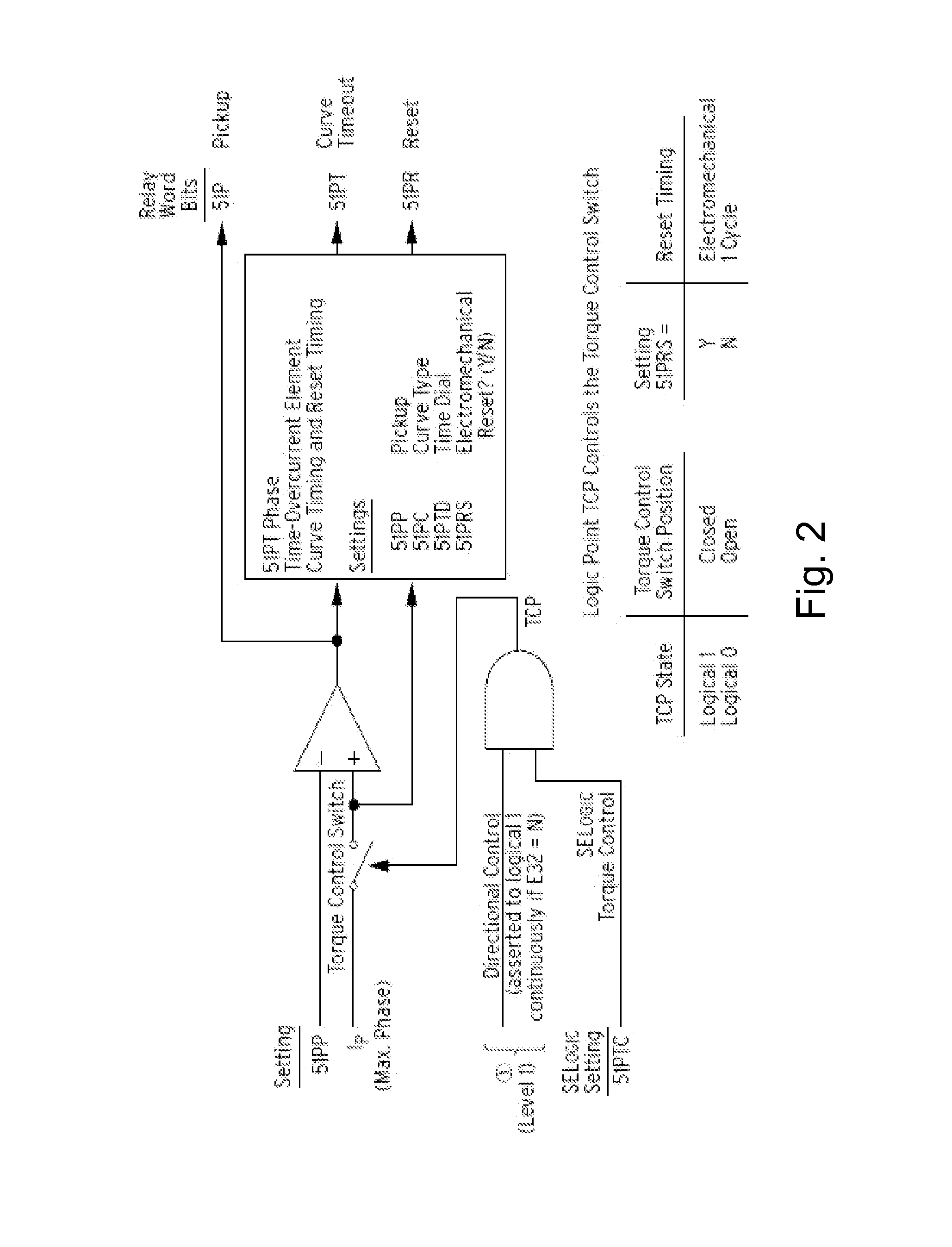
[0028]The figure is a flow chart of a visual dynamic monitoring system for operating states of a protective relay system according to a preferred embodiment of the present invention.

[0029]Referring to the figure, a visual dynamic monitoring method for operating states of a protective relay system comprises steps as following:

[0030]S100: obtaining information of a voltage input circuit and current input circuit of the protective relay system, internal information of a relay device, and information of a tripping and closing circuit, wherein

[0031]the information of the current input circuit and as well as voltage input circuit are collected by a collector specialized, and are output to a dynamic monitoring device via a communication port of the collector,

[0032]internal hardware & software logic states of computer based relays are read from a communication port of the relays by the dynamic monitoring system via a communication network, and

[0033]the information of the tripping and closin...


PUM


Abstract

A visual dynamic monitoring system for operating states of a protective relay system, which is applied to a computer based relay includes: collecting information of a voltage input circuit & a current input circuit and internal hardware & software of protection relay, as well as a tripping and closing circuit, to obtain real-time informations completely reflecting operating states of the protective relay system; analytically calculating the real-time information mentioned above according to the designed protection principle, forming logical relations having a time sequential characteristic among the real-time information with a result by the analytically calculating; and dynamically displaying the operating states of the protective relay system, so as to providing a supporting data for implementing an evaluation of the operating states of the protective relay system.

Description

BACKGROUND OF THE PRESENT INVENTION[0001]1. Field of Invention[0002]The present invention relates to a technical field of a power system, and more particularly to a visual dynamic monitoring system for operating states of a protective relay system.[0003]2. Description of Related Arts[0004]The rapid development of techniques in industries such as micro-electronics, computers and communications provides a basis for the application of a microcomputer-based protective relay device in a power system. The microcomputer-based protective relay plays a vital role for the stability of a power system. Hence the performance of a relay has critical effects on the safety and stability of the power system.[0005]The application of computer-based relay brings benefits for easy detecting the default of relays. However, an operation principle that a computer-based relay responding to a power system disturbance based on a digital signal processing technique turns a visible logic schematic view of an or...

Claims


Application Information

Patent Timeline
IPC IPC(8): H01H71/04G06F19/00
CPCH02H1/0053H02H1/0092
Inventor GAO, XIANG
Owner SHANGHAI YIHAO AUTOMATION CO LTD
Why Eureka
Try Eureka