Circumferentially constraining sutures for a stent-graft

a stent and circumferential constraining technology, applied in the field of endoluminal prosthesis or stent graft, can solve the problems of prolonging recovery period, high invasiveness, and inability to perform on individuals with fragile health or other contraindication factors, so as to reduce the diameter of the tubular body, reduce the diameter of at least a portion, and reduce the effect of the diameter

Active Publication Date: 2013-10-31
MEDTRONIC VASCULAR INC
View PDF29 Cites 57 Cited by
  • Summary
  • Abstract
  • Description
  • Claims
  • Application Information

AI Technical Summary

Benefits of technology

[0009]Embodiments hereof also relate to a method for temporarily reducing the diameter of at least a portion of a self-expanding stent-graft. The stent-graft includes a tubular body of a biocompatible graft material and a plurality of self-expanding stents. A first thread having a first thread loop and a second thread having a second thread loop are interlocked. The first thread at a first end opposite the first thread loop is attached to one of the stents. The first thread is extended around a first portion of the circumference of the tubular body and the second thread around is extended from the first thread around a second portion of the circumference of the tubular body. The second thread is pulled to cause the first loop of the first thread to move along the second portion of the circumference to reduce the diameter of the tubular body. A trigger wire is inserted longitudinally along the tubular body and through the first loop to retain the tubular body in a reduced diameter configuration after the second thread is removed.

Problems solved by technology

Such surgery is highly invasive, requires an extended recovery period and, therefore, cannot be performed on individuals in fragile health or with other contraindicative factors.
Further, when aneurysms are near branch vessels, the “landing zone” for the stent-graft may be limited such that accurate placement of the stent-graft is critical.
Thus, re-positioning the stent-graft after deployment is difficult.
However, with current devices, the stent-graft may jump out of position when the stent-graft is deployed.

Method used


Image

  • Circumferentially constraining sutures for a stent-graft
  • Circumferentially constraining sutures for a stent-graft
  • Circumferentially constraining sutures for a stent-graft

Examples


Embodiment Construction

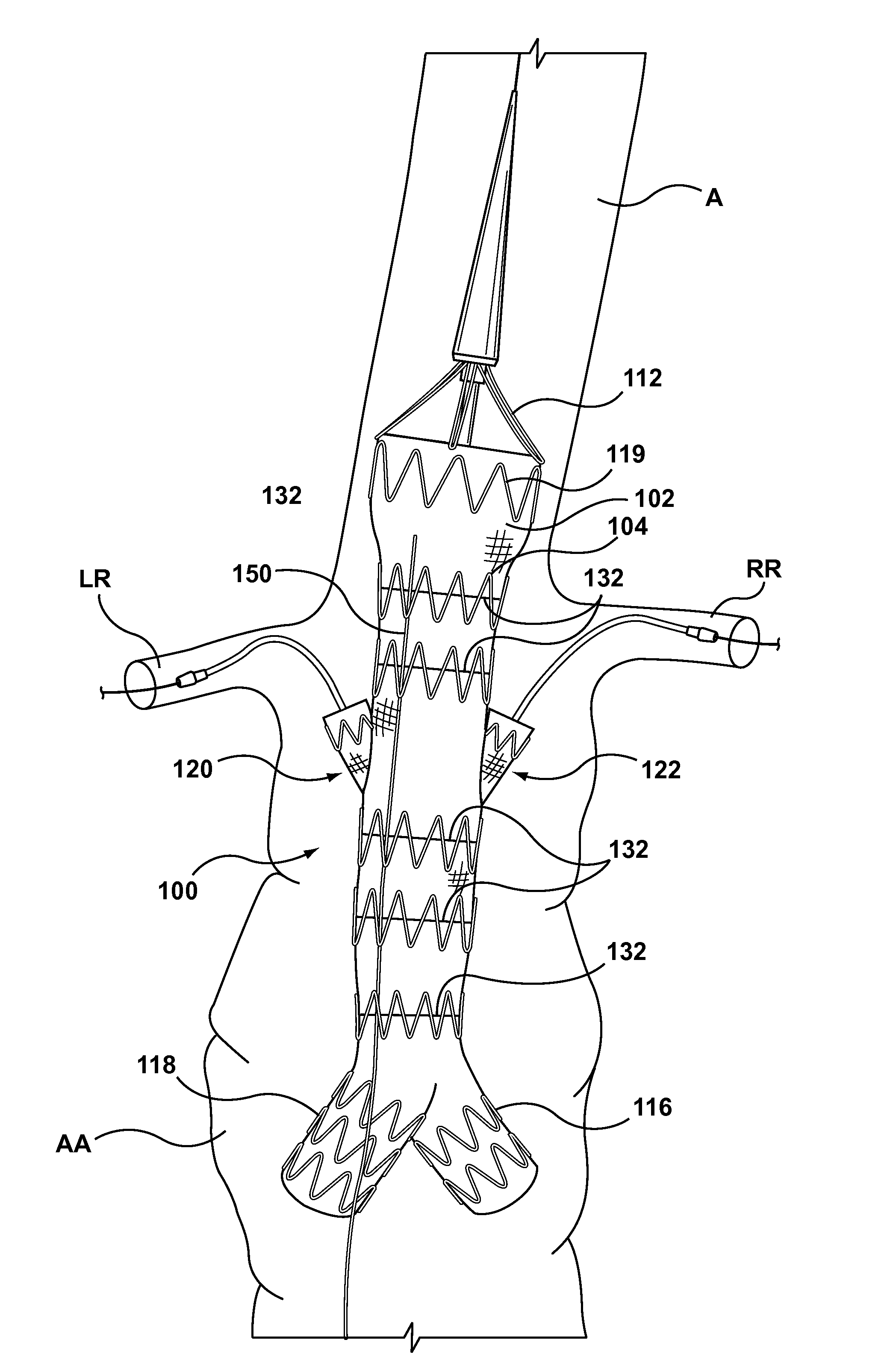
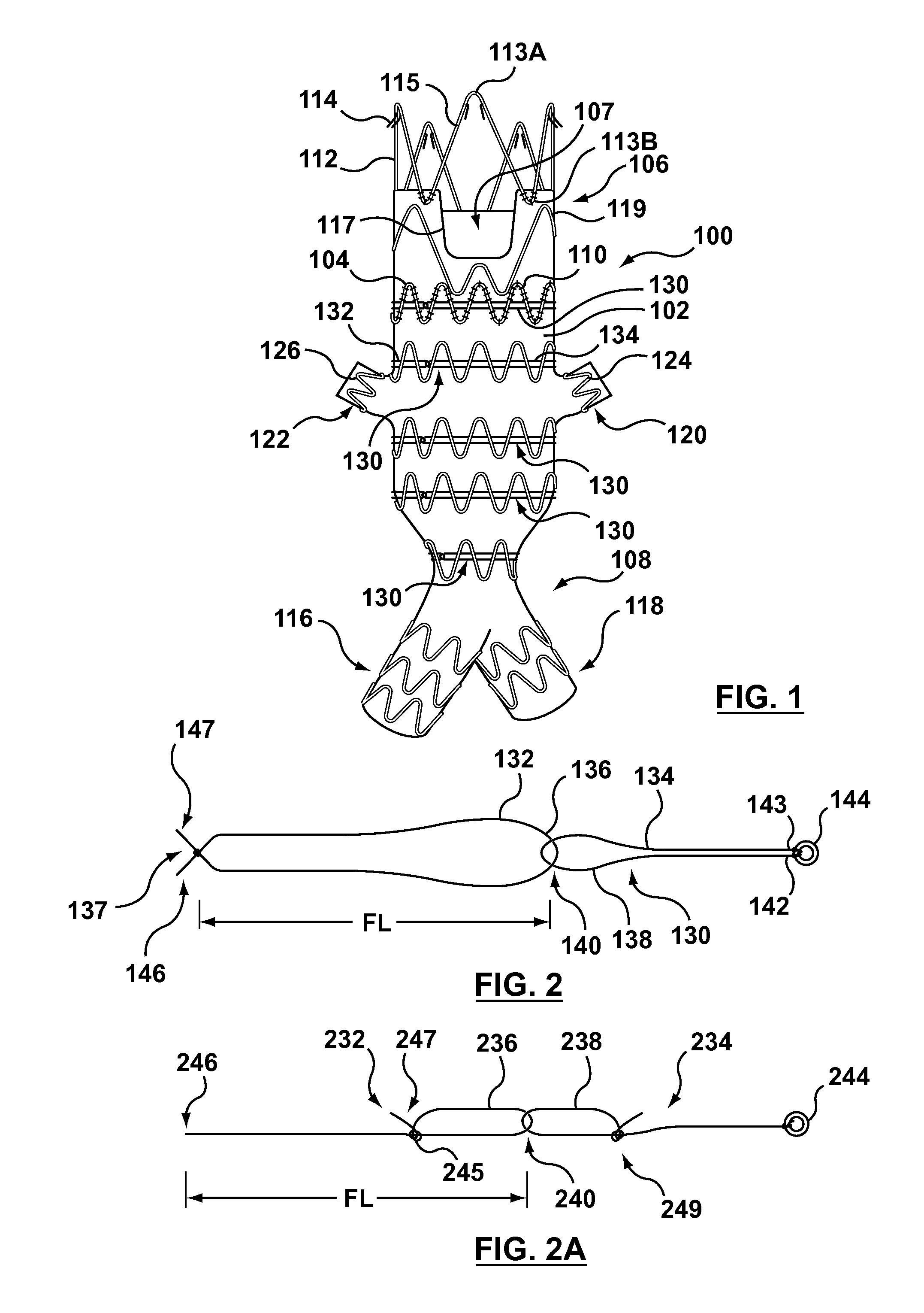
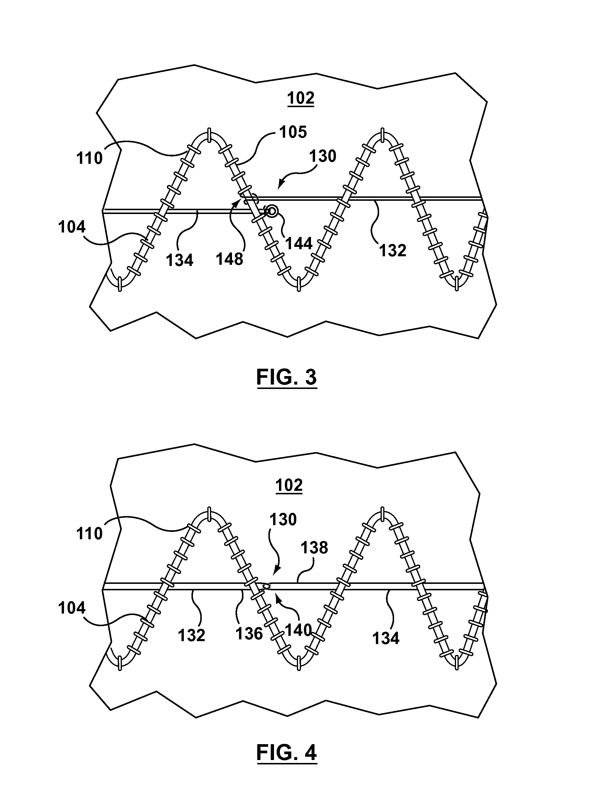
[0018]Specific embodiments of the present invention are now described with reference to the figures, wherein like reference numbers indicate identical or functionally similar elements. Specific embodiments are now described with reference to the figures, wherein like reference numbers indicate identical or functionally similar elements. Unless otherwise indicated, for the delivery system the terms “distal” and “proximal” are used in the following description with respect to a position or direction relative to the treating clinician. “Distal” and “distally” are positions distant from or in a direction away from the clinician, and “proximal” and “proximally” are positions near or in a direction toward the clinician. For the stent-graft prosthesis proximal is the portion nearer the heart by way of blood flow path while distal is the portion of the stent-graft further from the heart by way of blood flow path. In addition, the term “self-expanding” is used in the following description wi...


PUM

PropertyMeasurementUnit
lengthaaaaaaaaaa
diameteraaaaaaaaaa
diameteraaaaaaaaaa

Abstract

A circumferentially constraining suture for an endovascular prosthesis having a tubular body and a plurality of stents coupled to the tubular body includes a first thread coupled at a first end to one of the stents and a first thread loop disposed opposite the first end. The first thread extends only partially around a circumference of the tubular body in a radially expanded configuration. A second thread having a second thread loop is interlocked with the first thread loop and extends from the first thread loop around a remainder of the circumference of the tubular body. Pulling the second thread causes the first thread to circumferentially constrain the tubular body to a reduced diameter configuration. A trigger wire inserted through the first thread loop retains the first thread such that the tubular body is in the reduced diameter configuration after removal of the second thread.

Description

FIELD OF THE INVENTION[0001]This invention relates generally to endoluminal medical devices and procedures, and more particularly to an endoluminal prosthesis or stent-graft having circumferentially constraining sutures to circumferentially constrain the stent-graft for a partial deployment of the stent-graft.BACKGROUND[0002]Aneurysms and / or dissections may occur in blood vessels, and most typically occur in the aorta and peripheral arteries. Depending on the region of the aorta involved, the aneurysm may extend into areas having vessel bifurcations or segments of the aorta from which smaller “branch” arteries extend. Various types of aortic aneurysms may be classified on the basis of the region of aneurysmal involvement. For example, thoracic aortic aneurysms include aneurysms present in the ascending thoracic aorta, the aortic arch, and branch arteries that emanate therefrom, such as subclavian arteries, and also include aneurysms present in the descending thoracic aorta and branc...

Claims


Application Information

Patent Timeline
Patent Type & Authority Applications(United States)
IPC IPC(8): A61F2/82
CPCA61F2/07A61F2/954A61F2002/067A61F2002/075A61F2002/9511A61F2/9517Y10T29/49863
Inventor PEARSON, MEGHANSIMMONS, EMILIEPEARCE, STEPHENRUNDLE, STEPHANNIEZAVALA, ANA
Owner MEDTRONIC VASCULAR INC
Why Eureka
Try Eureka