Static Seal for Turbine Engine

Inactive Publication Date: 2014-01-02
SIEMENS ENERGY INC
View PDF3 Cites 4 Cited by
  • Summary
  • Abstract
  • Description
  • Claims
  • Application Information

AI Technical Summary

Benefits of technology

[0006]In accordance with an aspect of the invention, a seal structure is provided in a gas turbine engine having an axial gas flow therethrough, the seal structure being provided for minimizing gas leakage between a high pressure zone and a low pressure zone. The seal structure comprises first and second components located adjacent to each other and forming a barrier between the high and low pressure zones. A seal cavity is defined in the first and second components, the seal cavity extending to either side of an elongated gap extending generally in a first direction between the first and second components. A seal member is positioned within the seal cavity and spans across the elongated gap. The seal member comprises first and second side edges extending into each of the components in a second direction transverse to the first direction, and opposing longitudinal edges extending between the side edges generally parallel to the first direction. At least one of the side edges comprises at least one groove formed in the at least one side edge, and has a direction of elongation extending between the longitudinal edges, for effecting a reduction of gas flow around the seal member at the at least one side edge.
[0007]In accordance with a further aspect of the invention, a seal structure is provided in a gas turbine engine having an axial gas flow therethrough, the seal structure being provided for minimizing ga

Problems solved by technology

Mixing of these flows and gas leakage in general, from or into the gas

Method used


Image

  • Static Seal for Turbine Engine
  • Static Seal for Turbine Engine
  • Static Seal for Turbine Engine

Examples


Embodiment Construction

[0015]In the following detailed description of the preferred embodiment, reference is made to the accompanying drawings that form a part hereof, and in which is shown by way of illustration, and not by way of limitation, a specific preferred embodiment in which the invention may be practiced. It is to be understood that other embodiments may be utilized and that changes may be made without departing from the spirit and scope of the present invention.

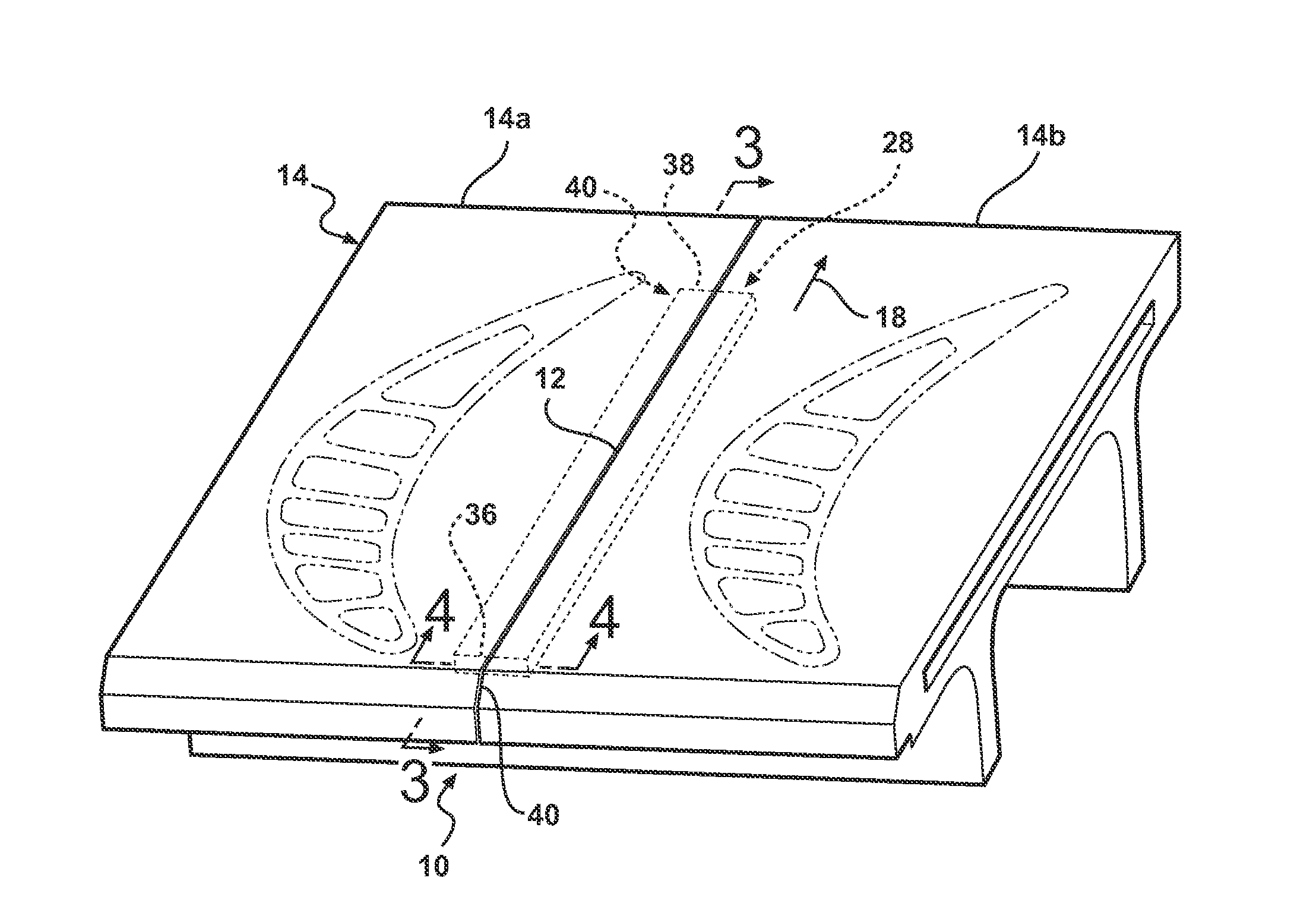
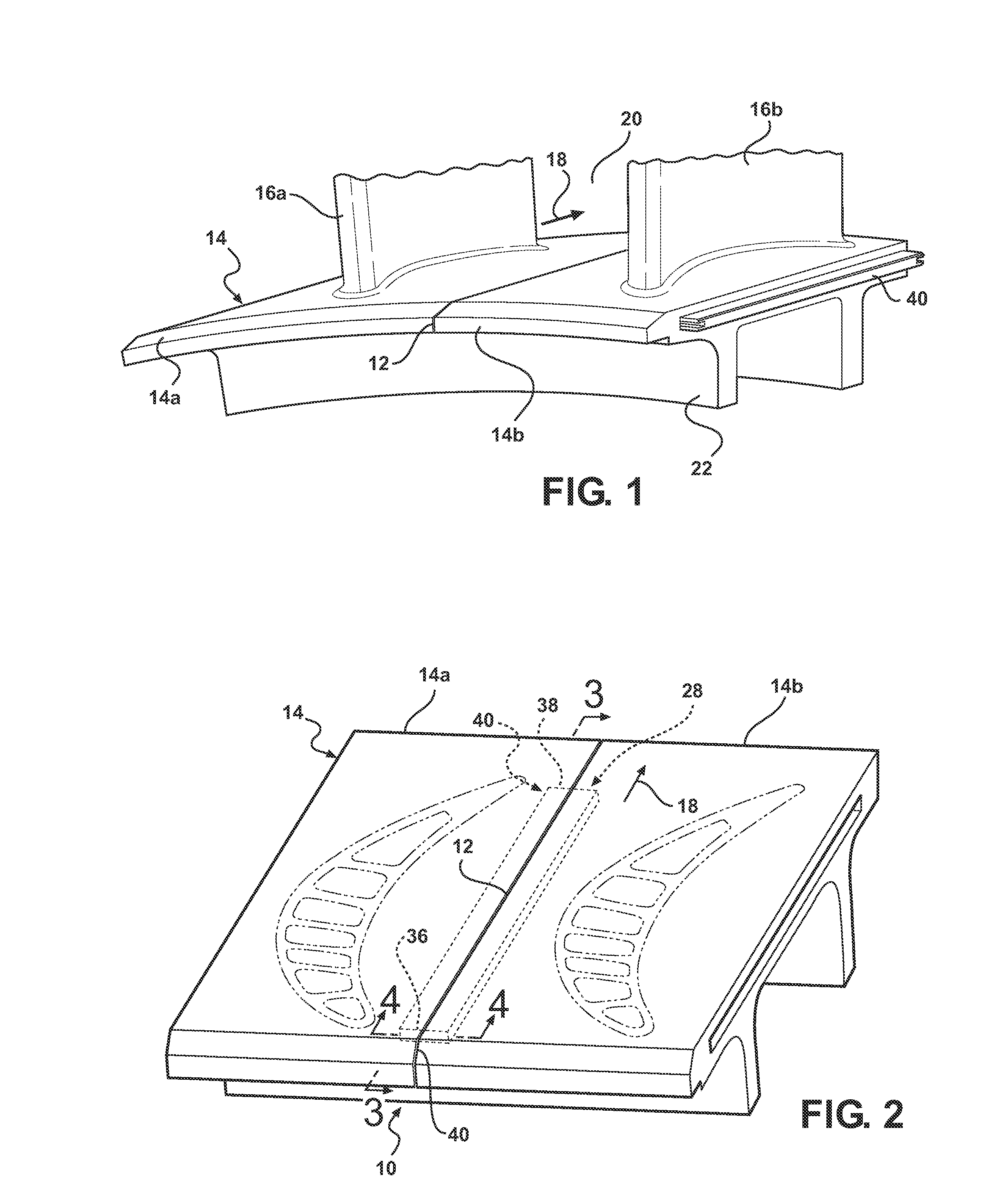
[0016]As seen in FIGS. 1 and 2, the present invention is directed to a seal structure 10 for sealing gaps 12 between adjacent first and second components, such as first and second turbine vane shroud segments 14a, 14b. The shroud segments 14a, 14b collectively form a shroud 14 in an engine, such as a gas turbine engine. The first and second shroud segments 14a, 14b may be associated with respective stationary vanes 16a, 16b. The shroud 14 defines an inner portion of a gas path for an axial hot gas flow 18, and forms a barrier separating ...


PUM


Abstract

A seal structure for a gas turbine engine, the seal structure including first and second components located adjacent to each other and forming a barrier between high and low pressure zones. A seal cavity is defined in the first and second components, the seal cavity extending to either side of an elongated gap extending generally in a first direction between the first and second components. A seal member is positioned within the seal cavity and spans across the elongated gap. The seal member includes first and second side edges extending into each of the components in a second direction transverse to the first direction, and opposing longitudinal edges extending between the side edges generally parallel to the first direction. The side edges include a groove formed therein for effecting a reduction of gas flow around the seal member at the side edges.

Description

[0001]This invention was made with U.S. Government support under Contract Number DE-FC26-05NT42644 awarded by the U.S. Department of Energy. The U.S. Government has certain rights to this invention.FIELD OF THE INVENTION[0002]The invention is directed generally to seals for separating gas paths in turbine engines and, more particularly, to static seals between adjacent components forming a barrier between gas paths of a turbine engine, such as components comprising turbine vane shroud assemblies.BACKGROUND OF THE INVENTION[0003]The main gas-flow path in a gas turbine engine commonly includes a gas intake, a compressor, a combustor, a turbine, and a gas outlet. There are also secondary flows that are used to cool the various heated components of the engine. Mixing of these flows and gas leakage in general, from or into the gas path, is detrimental to engine performance and is generally undesirable.[0004]One particular area in which a leakage path occurs is in the spacing between two ...

Claims


Application Information

Patent Timeline
IPC IPC(8): F01D11/00
CPCF01D11/005
Inventor SALAZAR, SANTIAGOGISCH, ANDREW
Owner SIEMENS ENERGY INC
Why Eureka
Try Eureka