Efficient reduction of inter-cell interference using RF agile beam forming techniques

a beam forming and inter-cell interference technology, applied in the field of large-area broadband networks, can solve the problems of insufficient video services for more than a handful of users, high data rates and increased capacity offered by 3g and 4g networks, and insufficient to meet current and expected bandwidth demands, etc., to achieve the effect of reducing the data rate offered to users located in the cell boundary area, affecting cell capacity and throughput, and affecting user experien

Active Publication Date: 2014-01-09
ALL PURPOSE NETWORKS INC
View PDF10 Cites 48 Cited by
  • Summary
  • Abstract
  • Description
  • Claims
  • Application Information

AI Technical Summary

Benefits of technology

[0005]A problem of note in wireless networks is the interference presented to users in one Cell coverage area by the signals transmitted by an adjacent Cell. This interference is called Inter-Cell Interference, and is especially encountered by users who are near the boundary between two adjacent Cells. The RF signal from each Cell necessarily overlaps the coverage area of the adjacent Cell, because otherwise, RF coverage holes result. The areas where the RF signals overlap are the areas in which Inter-Cell Interference occurs. Because of the interference, the data rates offered to users located in the Cell boundary areas may be reduced, and hence the Cell capacity and throughput, as well as the user experience, may be impacted in a negative way. In an LTE Wireless Network, users are assigned sub-carriers on which to transmit or receive their data. The sub-carrier sets are designed in the standards to be orthogonal to each other, so that users assigned to one set of sub-carriers observe no interference from the transmissions for other users who are assigned a different set of sub-carriers. However, near the Cell boundary, each of two adjacent Cells may assign the same set of sub-carriers to users in its respective Cell boundary area, which is part of its Cell coverage area. In this case, each of these users may be interfered with by the transmissions in the adjacent Cell that use the same sub-carriers as are assigned to the given user.
[0006]One current technique for reducing inter-Cell interference includes dividing the LTE band of sub-carriers into subsets, such that one subset of sub-carriers is assigned only to users near a boundary of the serving Cell, while the second subset is assigned to users located in the interior of the serving Cell. The subsets may be arranged in each of a set of adjacent Cells such that different subsets of sub-carriers are used at the boundary of these Cells. This approach results in lower Cell throughput and possibly lower maximum data rates, because not all of the LTE sub-carriers are available for assignment to any user. Another current technique uses inter-Cell communications to inform an adjacent Cell of the sub-carriers that are being assigned, so they may not be assigned by the adjacent Cell. This technique suffers from the added inter-Cell communications, a less than optimal Cell throughput, and possibly from lower maximum data rates that may be assigned to users.
[0007]The present disclosure describes a method of assigning beam rotation patterns in adjacent Cells for minimizing Inter-Cell Interference while allowing the complete set of LTE sub-carriers to be assigned to any user at any time, and without requiring additional Cell-to-Cell communications. This part of the disclosure pertains to a collection of Cells in an LTE wireless network that employs an Agile Beam Forming technique to transmit and receive RF signals. In an LTE FDD system, a set of sixteen RF beam sub-areas may be selected to cover the area normally covered by the Cell transmissions / receptions in an LTE FDD system that does not use Agile Beam Forming. Each sub-area is covered by the transmission (or reception) of a particular RF beam that is generated by the antenna system. In this instance, the set of sixteen RF beam sub-areas may be grouped into four subsets of four RF beam sub-areas each, where the geographical separation between sub-areas in the same subset is selected to be as large as possible. Within a given Cell using Agile Beam Forming techniques, it is then possible to assign the same set of sub-carriers to four different users who are located in different RF beam sub-areas, thus increasing the effective system bandwidth by a factor of up to four, and likewise, increasing the effective system throughput by a factor of up to four. Although an example using sixteen RF beam sub-areas broken into to four subsets is described, one skilled in the art will appreciate that other configurations may be used in implementation of the system, and as applied to the disclosed technique for reducing inter-Cell interference.
[0021]In embodiments, in each TTI in an FDD system, or in each D sub-frame in a TDD system, the MAC layer software and the PHY layer software may generate (N+1) digital data streams, where one corresponds to the transmit RF signal to be generated in the current TTI, and which covers the entire Cell (e.g., Cell-Wide transmit RF signal), and where each of the remaining N digital data steams corresponds to an RF transmit beam to be generated in the TTI. The MAC layer software may provide the PHY layer software with information regarding which transmit data stream to use to transmit a specific set of transport blocks using a specific set of PRBs, be they for common channels, or for user data. The PHY layer software may process the transport blocks received from the MAC layer software, placing the results in a transmit beam data stream, or in the Cell-Wide transmit data stream, in the interface to the RF and antenna system, per the instructions received from the MAC layer software.
[0027]In embodiments, in each TTI in an FDD system, or in each U sub-frame in a TDD system, the RF and antenna system may generate (N+1) digital data streams, where one corresponds to the received RF signal that covers the entire Cell (e.g., the Cell-Wide receive data stream), and where each of the remaining N digital data steams corresponds to an RF receive beam generated in the TTI. The MAC layer software may provide the PHY layer software with information regarding which receive data stream to process to receive a specific set of PRBs, be they for common channels, or for user data. The PHY layer software may present to the MAC layer software the results of its processing for each of the (N+1) receive signals, and for each result, may provide an indication of the receive beam data stream from which the result is obtained. By providing an indication of the receive beam data stream from which each result is obtained, the system allows the same PRB to be detected in multiple receive data streams.

Problems solved by technology

However, the popularity of data applications, and especially of video applications, is becoming so great that even the high data rates and increased capacity offered by 3G and 4G networks do not meet the current and expected demands for bandwidth.
Several factors combine to make it difficult to meet these user demands.
This is not enough to supply video services to more than a handful of users.
Furthermore, inter-cell interference caused by the overlap of RF signals between transmitting Cells reduces the data rates and capacities that may be provided to users who are located in the boundaries between Cells.
Facilities that operate at one Gbps may not be deployed to reach all base stations, and hence, a moderate number of users of video applications may easily use so much back haul bandwidth that other services cannot be provided to the remaining users.
Long packet transit delays (latency) between the service program that runs on the server and the user access point in the wireless network may result in a poor user experience in using the service.
It is becoming less attractive for the Government to use proprietary systems for their wireless communications needs.
This behavior may not be available in today's wireless networks to the degree required by the government.
A wireless network that has the ability to acquire, process, store, and redistribute the sensor data efficiently and quickly is not available.
A problem of note in wireless networks is the interference presented to users in one Cell coverage area by the signals transmitted by an adjacent Cell.
This interference is called Inter-Cell Interference, and is especially encountered by users who are near the boundary between two adjacent Cells.
The RF signal from each Cell necessarily overlaps the coverage area of the adjacent Cell, because otherwise, RF coverage holes result.
Because of the interference, the data rates offered to users located in the Cell boundary areas may be reduced, and hence the Cell capacity and throughput, as well as the user experience, may be impacted in a negative way.
In this case, each of these users may be interfered with by the transmissions in the adjacent Cell that use the same sub-carriers as are assigned to the given user.
This approach results in lower Cell throughput and possibly lower maximum data rates, because not all of the LTE sub-carriers are available for assignment to any user.
This technique suffers from the added inter-Cell communications, a less than optimal Cell throughput, and possibly from lower maximum data rates that may be assigned to users.

Method used


Image

  • Efficient reduction of inter-cell interference using RF agile beam forming techniques
  • Efficient reduction of inter-cell interference using RF agile beam forming techniques
  • Efficient reduction of inter-cell interference using RF agile beam forming techniques

Examples


Embodiment Construction

[0094]The following is a written description of the present disclosure, and of the manner and process of making and using it, in such full, clear, concise, and exact terms as to enable any person skilled in the art to which it pertains, or with which it is most nearly connected, to make and use the same, and sets forth the best mode contemplated by the inventors of carrying out the disclosure.

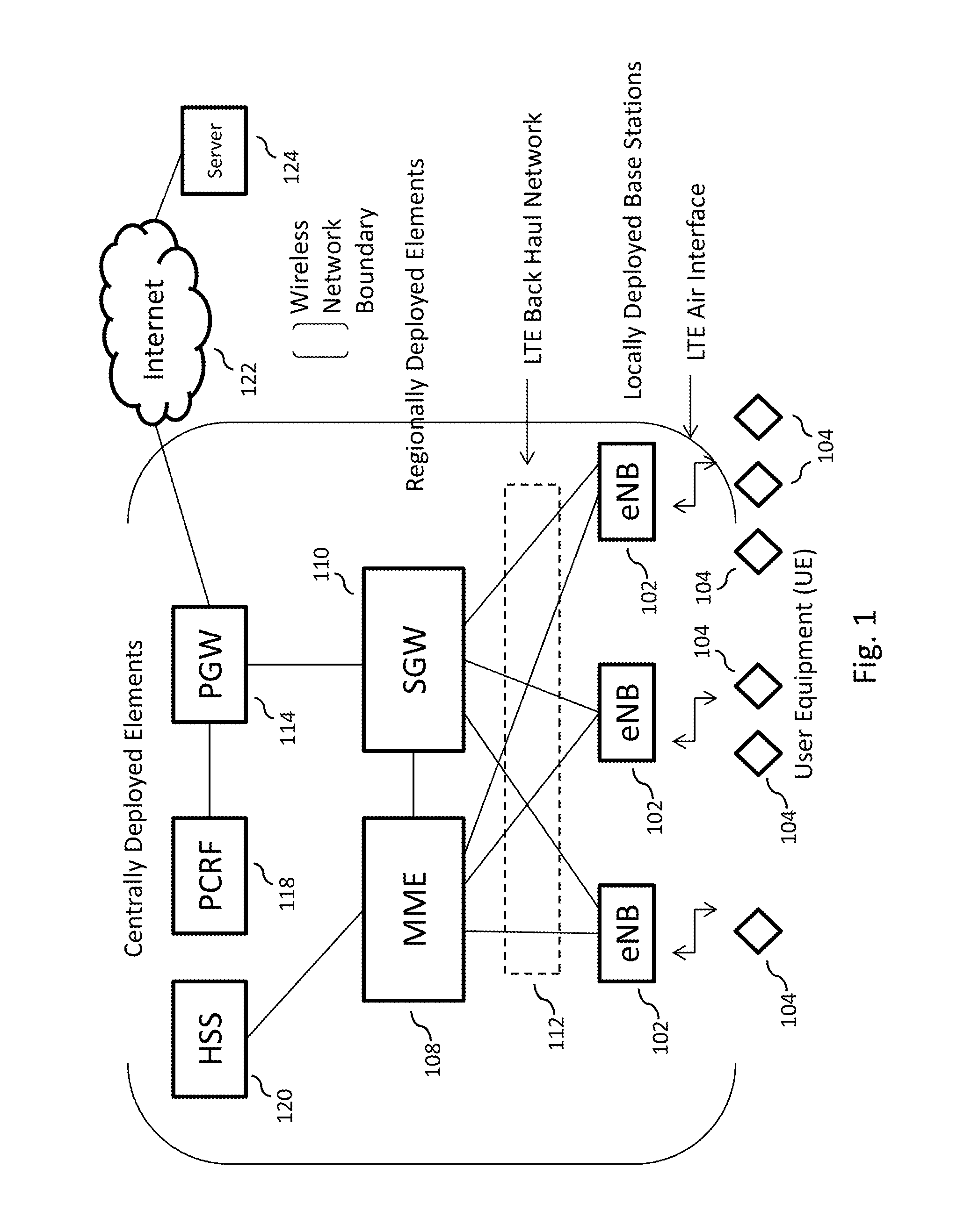
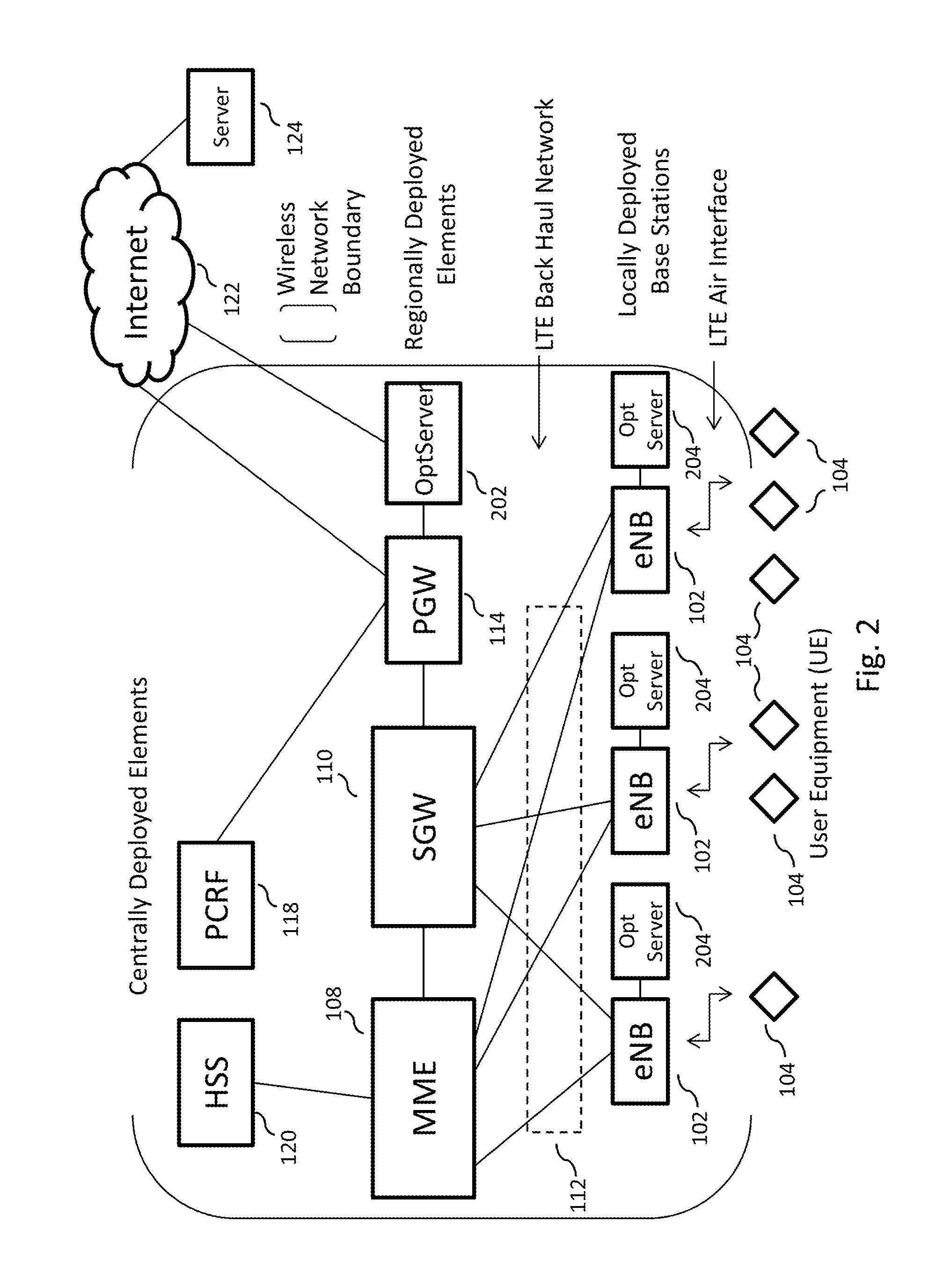
[0095]The present disclosure is related to a broadband wireless network, more specifically, to a multi-purpose network, alternatively referred to in this disclosure as an “All Purpose Network” or “APN,” that is capable of implementing a large scale (e.g., national) broadband wireless network to provide a very high wireless data capacity, and is capable of resolving all the issues described above. The APN may combine proven leading edge commercial wireless design and architecture methodologies with advanced RF technologies to substantially improve spectrum efficiency, spectrum usage, and data pe...


PUM


Abstract

In embodiments of the present disclosure improved capabilities are described for reducing inter-cell interference in a large area broadband LTE wireless network utilizing RF agile beam forming antennas, where the reduced inter-cell interference is realized by arranging the sets of rotating RF beams in each cell such that adjacent RF beam sub-areas in the same or in different cells are not illuminated at the same time. The reduction in inter-cell interference results in reduced interference noise for users located near the edges of cells, thereby allowing them to be assigned higher data rates. Also, the same set of sub-carriers can be assigned by adjacent cells to users located in the RF beam sub-areas at the cell boundaries, thereby allowing the complete set of LTE sub-carriers to be assigned to any user at any time, without requiring additional cell-to-cell communications.

Description

CROSS-REFERENCE TO RELATED APPLICATIONS[0001]This application is a continuation-in-part of U.S. patent application Ser. No. 13 / 945,273, filed Jul. 18, 2013, which is a continuation-in-part of U.S. patent application Ser. No. 13 / 916,338 filed Jun. 12, 2013, which is a continuation-in-part of U.S. patent application Ser. No. 13 / 860,711 filed Apr. 11, 2013, which is a continuation-in-part of U.S. patent application Ser. No. 13 / 755,808 filed Jan. 31, 2013, which is a continuation-in-part application of U.S. patent application Ser. No. 13 / 667,424, filed Nov. 2, 2012, which claims the benefit of U.S. provisional patent application 61 / 659,174, filed Jun. 13, 2012. All of these applications are incorporated herein by reference in their entirety.BACKGROUND[0002]This disclosure relates to broadband networks, and more specifically to methods and systems for increasing bandwidth in a large area broadband network.DESCRIPTION OF RELATED ART[0003]Wireless networks are deployed ubiquitously across ...

Claims


Application Information

Patent Timeline
Patent Type & Authority Applications(United States)
IPC IPC(8): H04W16/14
CPCH04W16/14H04J11/0056H04B7/0617H04J11/005H04W16/28H04B7/0408H04B15/00H04W72/046
Inventor RUBIN, HARVEYBREWINGTON, JAMES KEITHSAWKAR, ANIL S.POTICNY, DAVID M.
Owner ALL PURPOSE NETWORKS INC
Why Eureka
Try Eureka