Wide scan steerable antenna with no key-hole

a steerable antenna and wide-scan technology, applied in the field of steerable antennas, can solve the problems of increasing the complexity of the drive electronics system, requiring one rotary joint, and requiring more complex and costly drive electronics, so as to improve the reliability of the antenna system, and optimize the antenna geometry

Active Publication Date: 2014-04-17
MACDONALD DETTWILER & ASSOC INC
View PDF4 Cites 23 Cited by
  • Summary
  • Abstract
  • Description
  • Claims
  • Application Information

AI Technical Summary

Benefits of technology

[0006]An advantage of the present invention is that the architecture is capable of steering the beam on almost a full hemisphere (2 π steradians).
[0007]Another advantage of the present invention is that there are no singularities or key-holes within the coverage area, therefore avoiding the need for high speed actuation of the rotary actuators and the associated complexity and cost.
[0008]A further advantage of the present invention is that antenna architecture requires only a single RF signal rotary mechanism such as RF rotary joint or flex waveguide or flexible RF cable, therefore improving the reliability of the antenna system.
[0009]Still another advantage of the present invention is that the geometry of the antenna can be optimized to minimize the mass and size of the antenna moving parts.
[0010]Still another advantage of the present invention is that the stowed and dynamic envelope of the antenna can be optimized.
[0011]Yet another advantage of the present invention is that the shape of the reflectors, their relative position as well as their orientation can be optimized to provide the best mass, moving mass, stowed volume and swept volume. The beam generated by the main reflector does not have to be orthogonal to the axis defined by the feed source phase center and the center of the sub-reflector (feed axis). The angle of the beam with the feed axis should however be at least half of the angular width of the coverage area taken along the direction of its narrowest dimension.

Problems solved by technology

Some solutions have been developed to eliminate rotary joints in wide angle (essentially greater than 90 degrees) steerable antennas but they are affected by the presence of a singularity which affects the ability to track a target when the beam becomes substantially aligned with one of the rotation axes.
This can become a driver in the choice of the actuator and increase the complexity of the drive electronics system.
Larger rotary actuators with more complex and costly drive electronics are then required.
This approach has only one rotary joint but also suffers from the key-hole effect at nadir.

Method used


Image

  • Wide scan steerable antenna with no key-hole
  • Wide scan steerable antenna with no key-hole
  • Wide scan steerable antenna with no key-hole

Examples


Embodiment Construction

[0030]With reference to the annexed drawings the preferred embodiments of the present invention will be herein described for indicative purpose and by no means as of limitation.

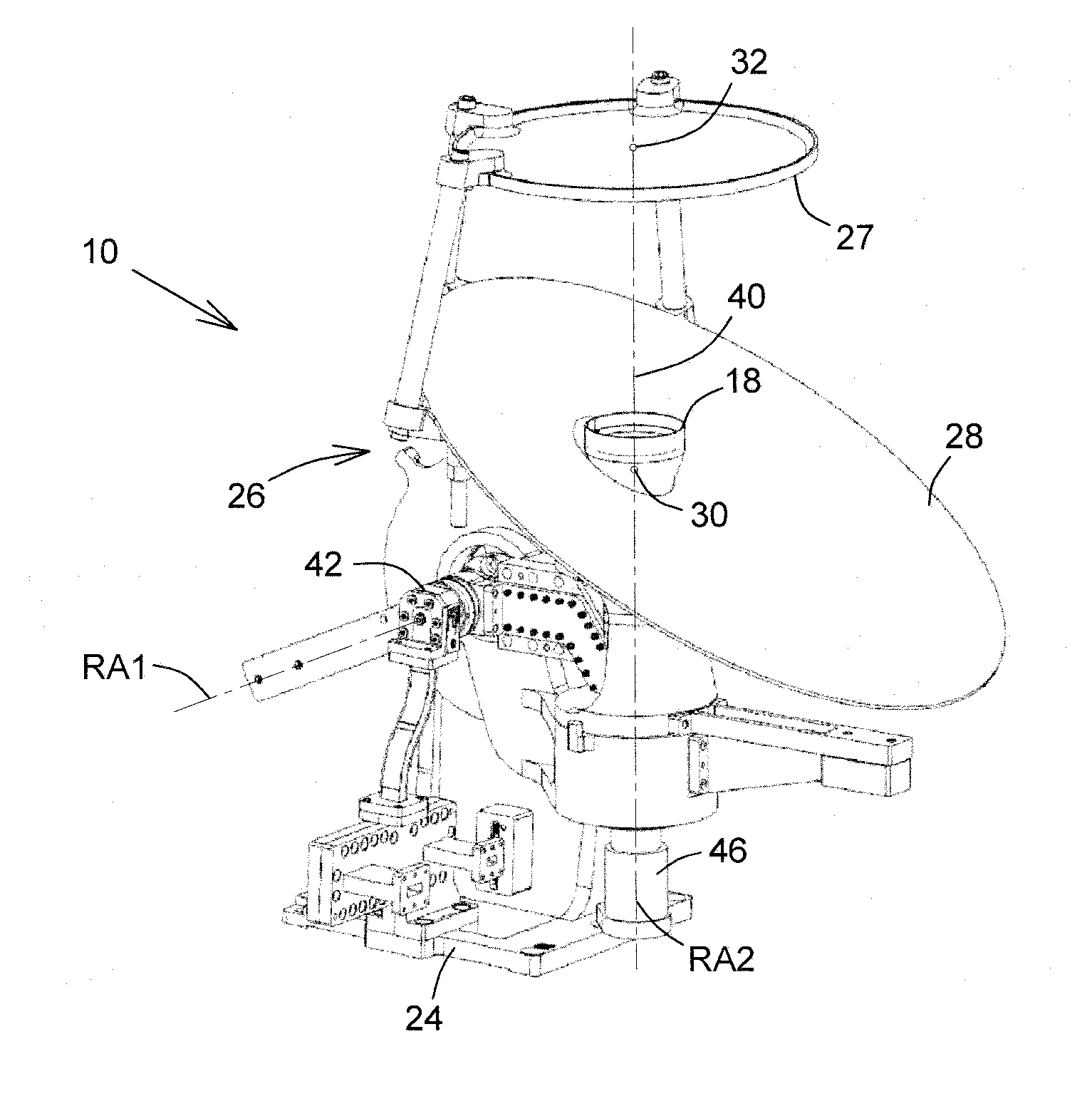
[0031]Referring to FIGS. 3 and 3a, there is shown a steerable antenna 10 for allowing transmission and / or reception of an electromagnetic signal within an antenna coverage region 14, as shown by the shaded area in FIG. 7, over a predetermined surface, such as the surface of the Earth. The electromagnetic signal travels through a feed chain and between a feed source 18 and a target. The target moves within the antenna coverage region 14 in which the antenna signal beam 12 is to be steered.

[0032]Although the antenna 10 described hereinafter is mounted on the earth facing panel 24 or deck of a satellite pointing at the Earth surface (not shown) with the target being a specific location thereon, it should be understood that any other configuration of a similar antenna such as a ground antenna facing at orbiting s...


PUM


Abstract

A steerable antenna architecture, or configuration, for optimal steering of transmitting and / or receiving beam over wide scan angles, is capable of steering the beam on a full hemisphere (2 π steradians), with no singularity or key-hole within a coverage area and with only one RF rotary joint. The architecture includes a dual-reflector assembly defining an antenna focal point located close to a main reflector surface and a signal feed chain having a signal source located adjacent to the antenna focal point and defining a feed axis substantially pointing towards a sub-reflector intersection point. A first actuator rotates the feed chain and the dual-reflector assembly about a first rotation axis generally perpendicular to the feed axis and not intersecting with the coverage area. A second actuator rotates one of the main reflector and the dual-reflector assembly about a second rotation axis aligned with the feed axis.

Description

CROSS-REFERENCE TO RELATED APPLICATIONS[0001]This application claims priority of U.S. Provisional Application for Patent No. 61 / 627,710 filed Oct. 17, 2011, the content of which is incorporated herein by reference in its entirety.FIELD OF THE INVENTION[0002]The present invention relates to the field of antenna systems, and is more particularly concerned with steerable antennas for transmitting and / or receiving electromagnetic signals.BACKGROUND OF THE INVENTION[0003]It is well known in the art to use steerable (or tracking) antennas to communicate with a relatively moving target over a wide scan angle. Especially in the aerospace industry, such steerable antennas preferably need to have high gain, low mass, and high reliability. The antennas used in these wide scan applications typically include two rotation axes requiring two rotary joints, cable cassettes or other means of propagating the signal over each of the rotation axis. The elimination or the reduction of the number of RF (...

Claims


Application Information

Patent Timeline
Patent Type & Authority Applications(United States)
IPC IPC(8): H01Q3/20
CPCH01Q3/08H01Q1/28H01Q3/18H01Q19/134H01Q19/19
Inventor CHOINIERE, ERICLIANG, AIPINGHORTH, RICHARDLOISELLE, PHILIPPE
Owner MACDONALD DETTWILER & ASSOC INC
Why Eureka
Try Eureka