Electronic control gears for LED light engine and application thereof

a technology of led light engine and electronic control gear, which is applied in the direction of lighting apparatus, electrical equipment, light sources, etc., can solve the problems of flicker phenomenon, relatively low power factor, and need for a more complicated and expensive driving circuit, so as to improve the flicker phenomenon, and reduce the total harmonic distortion

Inactive Publication Date: 2014-07-31
GRP TECH
View PDF6 Cites 27 Cited by
  • Summary
  • Abstract
  • Description
  • Claims
  • Application Information

AI Technical Summary

Benefits of technology

[0019]When the input voltage is higher than the energy storage capacitor voltage, the energy storage capacitor is charged with a first preset constant current for the capacitor voltage to reach an intermediate voltage level between Vf1 and Vf1+Vf2, where Vf1 and Vf2 stand for the forward voltage drop of the lowest and the second lowest LED array segments in the LED arrays, respectively. When the input voltage is lower than the energy storage capacitor voltage, the energy storage capacitor is discharged with a second preset constant current to light up the lowest LED array segment only during the dead time to improve the flicker phenomenon.
[0020]The dummy load provided by the invention embodiment comprises a controlled switch and a resistive load. The controlled switch electrically couples the resistive load to the two DC output terminals of the rectifier only within the dead time, and then cuts off the resistive load. The resistive load draws a line current only during the dead time to decrease the total harmonic distortion by means of stuffing up the dead time in the line current waveform for eliminating the discontinuous or jumping points.
[0021]Only during the dead time, the controlled switch is turned on to connect the resistive load to the two DC output terminals of the rectifier. Elsewhere, the controlled switch is shut off to disconnect the resistive load from the two DC output terminals of the rectifier. Therefore, the dummy load can effectively help decrease the total harmonic distortion with no significant loss of power efficiency due to resistive consumption.

Problems solved by technology

Traditional LED drivers usually come along with three application problems.
The first problem would be the need for a more complicated and more expensive driving circuit consisting of a filter, a rectifier, and a power factor corrector (PFC), etc. to drive LEDs.
The second problem would be the flicker phenomenon due to no current flowing through the LEDs during the dead time.
The third problem would be a relatively lower power factor exhibited by a low-power PFC with a loop current too weak to be precisely sensed to correctly shape the AC input current into a sinusoidal waveform.
If the loop current goes too low to be precisely sensed by the current sense circuitry in the PFC stage, the PFC would fail to properly keep the line current in phase and in shape with the line voltage to achieve a high power factor.

Method used


Image

  • Electronic control gears for LED light engine and application thereof
  • Electronic control gears for LED light engine and application thereof
  • Electronic control gears for LED light engine and application thereof

Examples


Embodiment Construction

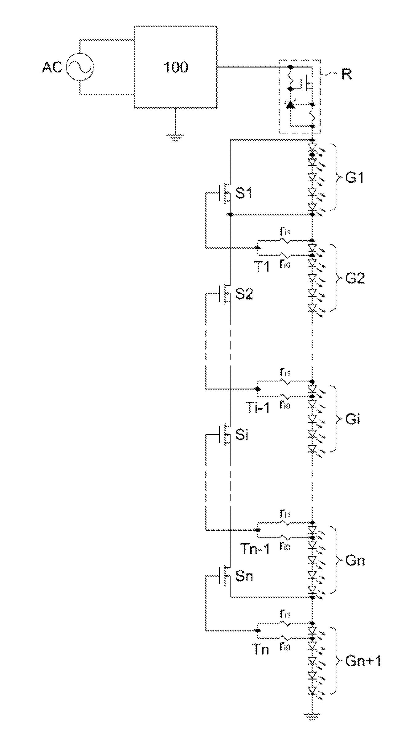
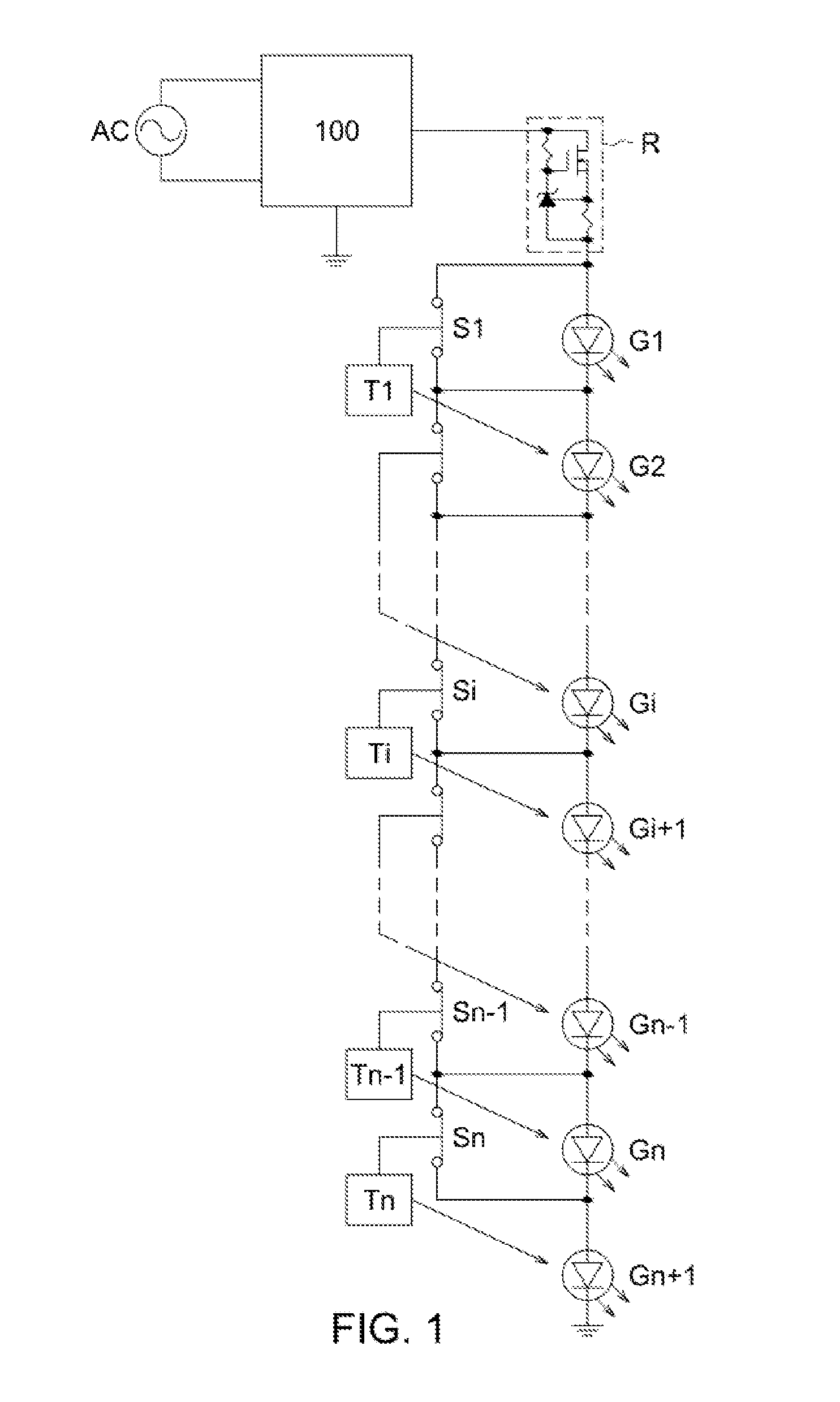
[0035]By nature, LEDs operate off of DC sources. As such, an AC sinusoidal voltage source would normally be rectified by a rectifier (such as a full-wave or half-wave rectifier) into a DC pulsating voltage source before being applied to an LED lighting device.

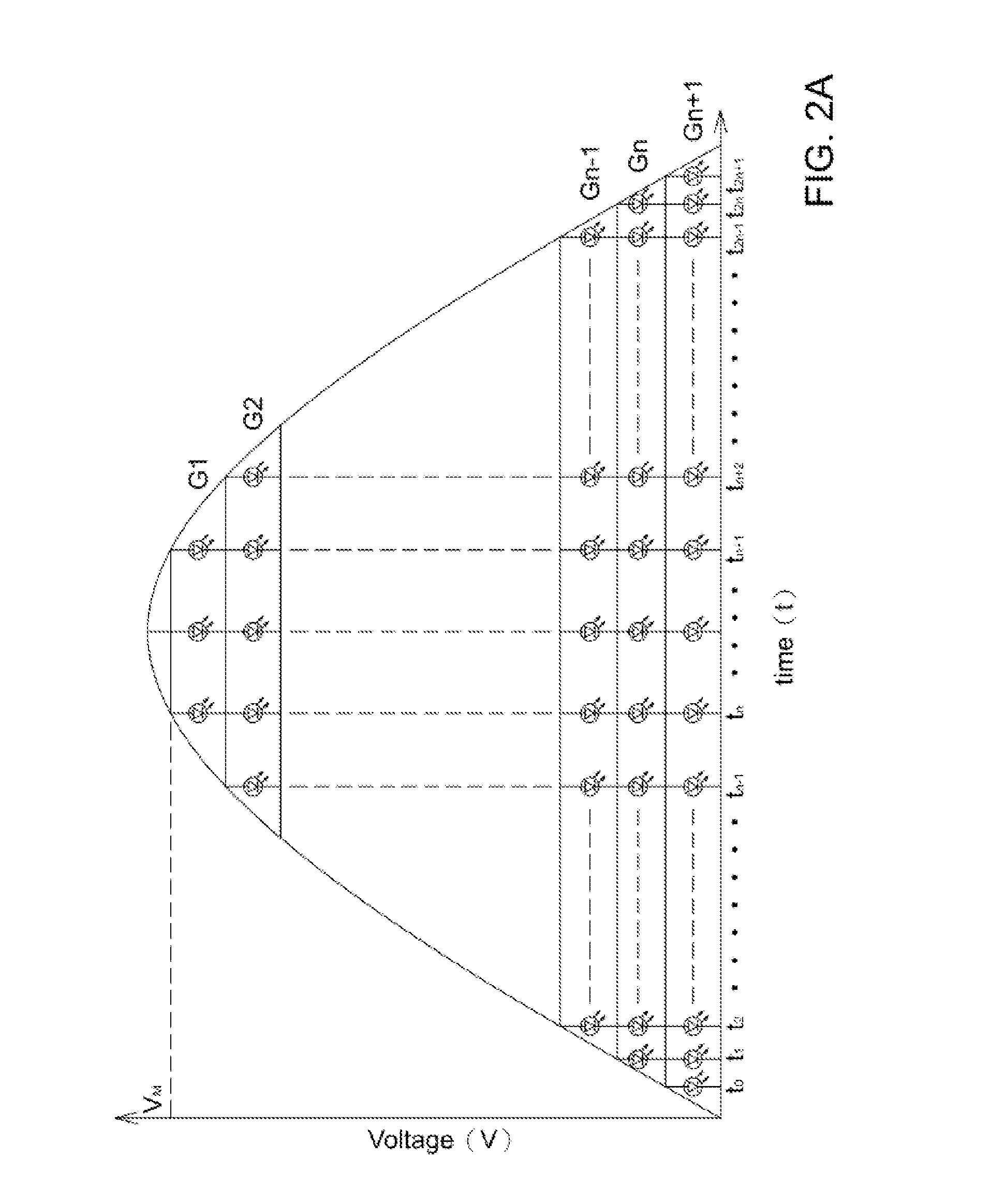
[0036]Similar in the unidirectional conduction property to an ordinary diode, an LED needs to get forward-biased, i.e. its forward voltage drop must be overcome by the rectified sinusoidal input voltage, before being able to be lit up by an exciting current. The partial period during which no current flows through the LED(s) is generally referred to as the dead time. The partial period during which current flows through the LED(s) is generally referred to as the conduction angle. The dead time in union with the conduction angle constitutes a full period of the rectified sinusoidal input voltage. The power factor is a measure of the similarity in both phase and shape between the line current and the line voltage. When an LED arr...


PUM


Abstract

Disclosed are electronic control gears for LED light engines able to improve power factor by way of gearing up or down the LED current and the AC input current in response to and in synchronization with the AC input voltage. Moreover, the disclosed electronic control gears could further reduce flicker phenomenon and total harmonic distortion when used in collocation with disclosed valley fillers, filling the LED current valleys only during the dead time, and in conjunction with disclosed dummy loads, ramping up or down the AC input current only during the dead time.

Description

BACKGROUND OF THE INVENTION[0001]1. Field of the Invention[0002]The invention relates to electronic control gears for LED (light emitting diode) light engine. In particular, the electronic control gears for LED light engine use the normally closed electronic switches to gear up or down the number and current of excited LEDs in the LED array segments in accordance with the level of the AC input voltage in order to improve the power factor. Furthermore, valley fillers and / or dummy loads can be optionally added in to improve the flicker phenomenon and / or decrease the total harmonic distortion, respectively.[0003]2. Description of the Prior Art[0004]As compared with the traditional lighting devices, the LED has a higher luminous efficacy. The LEDs can give off more than 100 lumens per watt because less electric energy is converted into waste heat. In sharp contrast, a traditional bulb only gives off about 15 lumens per watt because more electric energy is converted into waste heat. More...

Claims


Application Information

Patent Timeline
Patent Type & Authority Applications(United States)
IPC IPC(8): H05B33/08H05B44/00
CPCH05B33/083H05B45/48
Inventor YU, CHING SHENGWANG, CHIH LIANGCHEN, KUANG HUI
Owner GRP TECH
Why Eureka
Try Eureka